Full company details
McPHERSON
 7 Stuart Rd., Ste. A
Chelmsford, MA 01824-4107
United States
Phone: +1 978-256-4512
Fax: +1 978-250-8625
Toll-free: +1 800-255-1055
Measuring Diffraction Grating Efficiency
Photonics Spectra
Feb 2018A novel spectral test station can assess diffraction grating efficiency at specific wavelengths by simultaneously indexing incident wavelength and the unit being tested.ERIK SCHOEFFEL, MCPHERSON
Diffraction gratings are in most optical spectrometers covering visible, IR and UV spectra. Absorption and emission spectrometers, fluorimeters, inductively coupled plasma instruments and high-performance liquid chromatography equipment all use grating spectrometers. Large monochromators in fusion research, high harmonic generation for attosecond physics and synchrotron radiation all measure very short wavelengths of light in the UV and even extreme UV and soft x-ray wavelengths. Diffraction gratings in extraterrestrial instruments and astronomical telescopes allow light from objects in space to be analyzed spectroscopically. Such gratings tune laser wavelengths and stretch or compress laser pulses
1.
Improvements in the development of gratings and their coatings require knowledge of characteristics only obtained by measuring efficiency at the wavelength and in the geometry of use. It applies to burnished or ruled and replica diffraction gratings, as well as holographic, ion-milled and other groove profile and manufacturing techniques. The polarizer also allows direct measurement S-polarization, which does not follow cosK dependence like P-plane
2. UV gratings for applications such as thermonuclear fusion’s promise of clean energy, phosphors for more efficient lighting and semiconductor light sources to fit more features on smaller silicon chips all benefit from improved analytical instruments and diagnostic metrology in the deep and vacuum ultraviolet.
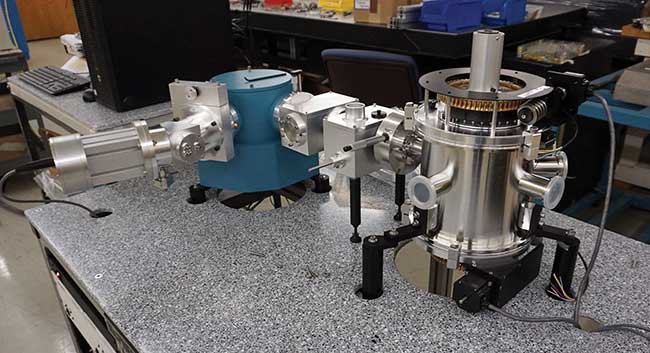
Figure 1. A vacuum- and purge-capable spectrophotometer configured as a spectral test station for measurement of plane diffraction grating efficiency and polarized response. Courtesy of McPherson.
The spectral test station for the measurement of plane diffraction grating efficiency and polarized response calculates the diffraction efficiency for gratings or witness parts between 10 to 50 mm
2 (Figure 1). The sample chamber has software to control grating angle of incidence. The motorized detector can scan through a range of angles or wavelengths as calculated according to groove density. The grating angle and incident wavelength scan synchronously to quickly collect grating efficiency in the selected diffracted order.
Design considerations
The spectral test station for measuring plane diffraction grating efficiency and polarized response has many advantages, not the least of which is the sytem’s simplicity and reliability
3. It measures in conditions that approximate those of actual use.
Most diffraction gratings are on plane blanks that do not focus. The monochromatic measuring beam is nearly collimated, before and after the diffraction grating surface. When interacting with the grating grooves, the incident light is diffracted. It follows the grating equation: m•λ/2•d•cos(σ), where order (m), groove density (d), incident wavelength (λ) and angle of incidence (σ) are known. The system uses a measuring spot approximately 1 cm
2 in the center of the test grating. The entire ruled area should be uniformly illuminated if testing for space flight or other critical applications. When it is desirable to know the variation in efficiency over the surface, one can make a number of measurements to map the efficiency as a function of position.
The motions required for testing gratings are simple rotation about a vertical axis perpendicular to the optical axis of the monochromator that passes through the apex of the test grating. The sample holder datum edge positions the front surface at the point of rotation. System tests measured efficiencies of plane gratings at angles of incidence from about 7 to 30 degrees and for wavelengths between 120 and 300 nm.
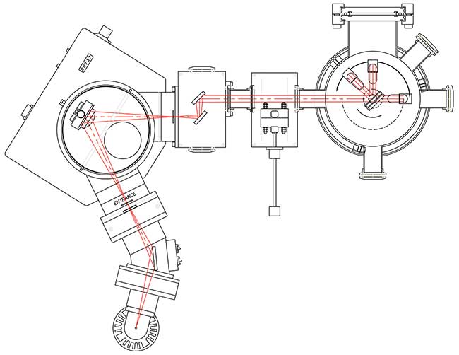
Figure 2. Schematic of the vacuum- and purge-capable spectrophotometer configured as a spectral test station for measurement of plane diffraction grating efficiency and polarized response. The rotatable detector is shown in several positions in the sample chamber. In this system, the grating may be at a fixed angle of incidence relative to the monochromator beam, allowing the photomultiplier tube to rotate independently about it, or the angle of incidence and the observed diffraction angle to change simultaneously. Courtesy of McPherson.
The test station has three main sections: a monochromatic illuminator; beam delivery optics and polarizer; and the sample chamber (Figure 2). In the sample chamber, a scintillator and light pipe can rotate around the grating being tested. They homogenize the signal, reducing photometric errors caused by nonuniform photocathodes in the photomultiplier and other detectors. The grating (sample) mount can be linearly translated out of the beam. When out of the beam, the detector receives the radiation from the monochromator exit slit and beam delivery optics, I
0. It is the ratio of this reference intensity incident on the grating to the diffracted that provides a result as percent efficiency. The polarizer is in the beam when desired and can easily be inserted or retracted under vacuum or purge conditions.
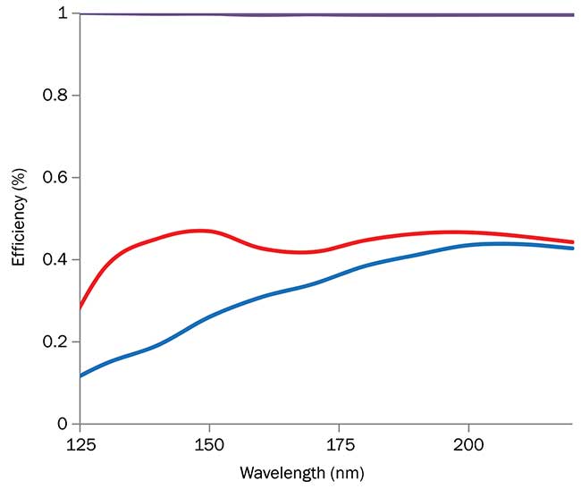
Measured diffraction grating efficiency of 1200-g/mm (red) and 1000-g/mm (blue) diffraction gratings in the deep UV, below 200 nm. At these wavelengths, the nature and quality of the reflection coating applied to the grating surface play a significant role in performance. Courtesy of McPherson.
To measure reflection efficiency, the grating is placed in the measuring position and rotated to desired angle of incidence. Software settings allow setting and control of the diffracted order, scan start and end wavelengths and increment, or wavelength step size. Software indexes wavelength from the monochromatic illuminator and angular position of the grating under test. The measured value and reference make a ratio for results in percent reflectance. This is an absolute test system because results are not relative to another coated witness part or sample. This is a more meaningful figure of merit in wavelength regions where photo degradation and contamination play a marked role in optic performance
4.
Detector rotation in the sample chamber is possible from zero (blocking the incoming beam) to 180 degrees, the transmission testing position. The limitation to angle of incidence comes from scintillator and beam size. High sample angles are limited by signal-to-noise ratio, as beam size must be reduced to make a smaller footprint at the sample for reduced apparent area of samples when rotated to high angles. One is able to rotate the grating to about 65 degrees without any difficulty or loss of fidelity in results.
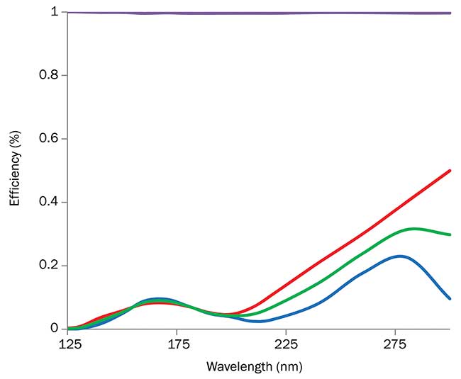
Polarized and average response for a 2400-g/mm replicated holographic diffraction grating. The deep-UV traces are S- (red), P- (blue) and average (green) response for a visible-wavelength optimized grating. Courtesy of McPherson.
One disadvantage is the long path length from source to detector. The measurement may be affected by unstable or residual gas pressure in the vacuum system. At pressures of 10
-5 or 10
-6 Torr, this is not a problem. At pressures of 10
-4 Torr or higher, some error may be introduced by absorption. An efficient pumping system or a good source of dry nitrogen gas for purging is essential. When purging, levels of water vapor and residual oxygen should be less than 10 ppm for reproducible measurements. Purge as opposed to vacuum operation minimizes photodegradation or drift due to optics contamination.
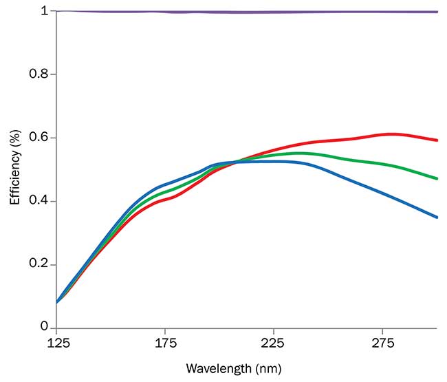
Polarized and average response for a 2400-g/mm replicated holographic diffraction grating. The deep-UV traces are S- (red), P- (blue) and average (green) response for a UV (200 nm) optimized grating. Courtesy of McPherson.
With the sample chamber light pipe and detector configuration, there is a left-right reversal of the probe beam on the scintillator between the measurement of the reference and diffracted beams. If both beam and detector are nonuniform, the measured efficiency may be in error. Fortunately, the scintillator and the light path through the light pipe homogenize the light beam. This minimizes influence of detector photocathode nonuniformity and consistently improves measurement results.
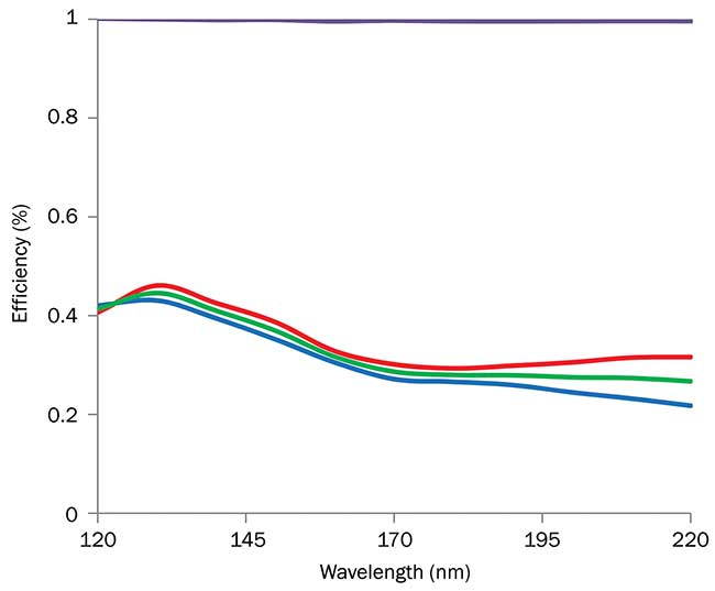
Polarized and average response for a 2400-g/mm replicated holographic diffraction grating. The deep UV traces are S- (red), P- (blue) and average (green) response for a blazed holographic grating with aluminum with magnesium fluoride coating (data courtesy of Shimadzu Corp.). Courtesy of McPherson.
The spectral test station for measuring plane diffraction grating efficiency and polarized response provides accurate results. It is built on a proven absolute spectrophotometer design. Parts are measured in their geometry of actual use and there is no need to use witness (reference reflective) samples. This increases confidence and certainty in measurements, as results do not depend on the quality or changes to the performance of reference parts in the deep ultraviolet where references are prone to photo- or other environmental degradation. The polarizer further increases utility. Operated by software, the system provides an easy-to-use and stable platform for optical characterization of diffraction gratings in the deep ultraviolet.
Meet the author
Erik Schoeffel is global sales and marketing director for McPherson. He holds a bachelor’s degree in industrial engineering from
Rowan University; email:
[email protected].
Acknowledgments
Thank you, D.M. Schoeffel (1931-2017), for helpful discussions; David Riley for assembling and operating the deep-UV spectrophotometer; and Bob Rhoads and Ed Holz for software support. Thanks to Yoshitaka Makino of Shimadzu Corp. for providing grating data and feedback about the user experience.
References
1. C. Palmer (1995). Diffraction gratings, the crucial dispersive component.
Spectroscopy, Vol. 10, Issue 2, pp. 14-15.
2. Spectra-Physics. Technical Application Note 15, Dependence of blaze wavelength of diffraction grating on deviation angle.
3. McPherson. Technical data sheet, VUVAS 1000 Spectrophotometer.
4. Y. Qu et al. (2009). The second order diffraction efficiency measurements in the vacuum ultraviolet.
Opt Exp, Vol. 17, Issue 15, pp. 13187-13192.