Full company details
Mitutoyo America Corp.
 965 Corporate Blvd.
Aurora, IL 60502
United States
Phone: +1 630-820-9666
Fax: +1 630-978-5394
Toll-free: +1 888-648-8869
High-Speed 3D Inspection with Liquid Lenses
Photonics Spectra
Nov 2019Liquid lenses can be synchronized with high-power lasers and coupled with high-speed image processing for enhanced materials processing and Industrial IoT responsiveness.VAHAN SENEKERIMYAN, PAUL GLADNICK, AND PAUL NUARA, MITUTOYO AMERICA CORP.
The concept of liquid lenses, which involves controlling the shape of a liquid to alter the properties of a lens, is not new. The human eye uses this concept every day as it focuses on objects near and far. The ciliary body of the human eye contains ciliary muscle, which alters the shape of the lens to alter the eye’s focusing ability and enables a person to focus on objects at varying distances. Researchers and engineers have applied this capability to liquid lenses and have commercialized the technology so that liquid lenses can be incorporated into microscopes, metrology inspection systems, cellphone cameras, diagnostic equipment, and more.
The ability to control the focal length of a lens at ultrahigh speeds in the focal range required by an application is tremendously valuable. Many scientific, industrial, and commercial applications demand fast modulation and control over the focus of the lens to enable high-speed illumination and measurements. For example, in noncontact inspection systems, the traditional approach requires mechanically moving the lens assembly to measure the sample along its height (Figure 1). However, this is often one of the bottlenecks that affect the speed of measurement and the overall inspection throughput.
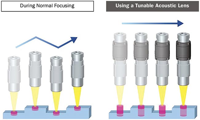
Figure 1. Schematic of a 3D noncontact measurement using a standard inspection system (left) and a tunable acoustic gradient lens (right). The tunable lens has no mechanically moving parts in the inspection solution, which simplifies the hardware and improves inspection throughput. Courtesy of Mitutoyo.
Over the past several years, various adaptive optics technologies have been developed to tackle this problem, including one solution that involves using a liquid to focus light. And although the goal of using an adaptive lens is to modulate the focus in a controllable fashion, liquid lenses vary in how they achieve this goal.
In the early 2000s, the commercialization of liquid lens technology began with a variable focus lens that used electrowetting as its method of altering the shape of liquid. Electrowetting is a technique that involves the use of two fluids of a similar density and a different refractive index (typically water and oil). One fluid acts as a conductor while the other acts as an insulator. The shape of the interface between these two fluids is controlled by applying a voltage.
The advantages of this technology are its compact design, low power consumption (tens of milliwatts), relatively large optical power range (e.g., 20 diopters)
1, and low manufacturing costs. The main drawbacks are its aberrations
2 and relatively low focusing speed, on the order of 100 Hz. When temperature in the environment varies, these lenses may be susceptible to a gravity-induced coma depending on the lens orientation. Such aberrations may restrict applications such as robotics because of the many possible orientations required for a robotic arm. In addition, the focusing speed is insufficient for a variety of high-speed inspection, metrology, laser material processing, and other applications.
Another type of variable focus lens hit the market around 2010. It used an optical fluid in a chamber with a flat side on one end and an elastic membrane made from polymer on the other
3. This type of lens alters the shape of the fluid through three different methods. The first pumps the fluid in and out of the chamber to alter the curvature of the lens. The second changes the aperture of the lens with a device similar to an iris diaphragm. The third applies pressure on the outside of the chamber through mechanical or electrical means. This type of variable focus lens typically has clear aperture in the range of 10 to 20 mm and an optical power range around 5 diopters. These lenses are dimensionally larger and consume more power (a few watts) compared to lenses based on electrowetting technology. And the relatively low cost of manufacture makes mass production of these lenses feasible. Yet, like lenses based on the electrowetting principle, the main disadvantages of this technology are its aberrations and relatively low focusing speed.
In 2011, a new liquid lens technology, initially developed at Princeton University, was introduced to the market: a tunable acoustic gradient (TAG) index of refraction lens
4-6.
TAG lenses
The TAGLENS (its trademarked name) consists of a cylindrical cavity in a hollow piezoelectric tube that has transparent windows on both sides and is filled with an optically transparent fluid (Figure 2a). The selection of the fluid type depends on the spectral range and intensity of the incident light, as well as on the thermal and viscous properties of the fluid. The cavity is driven by an AC signal leading to strong vibrations in the radial direction (Figure 2b). Following are the fundamentals of how this acoustically driven fluid acts as a lens.
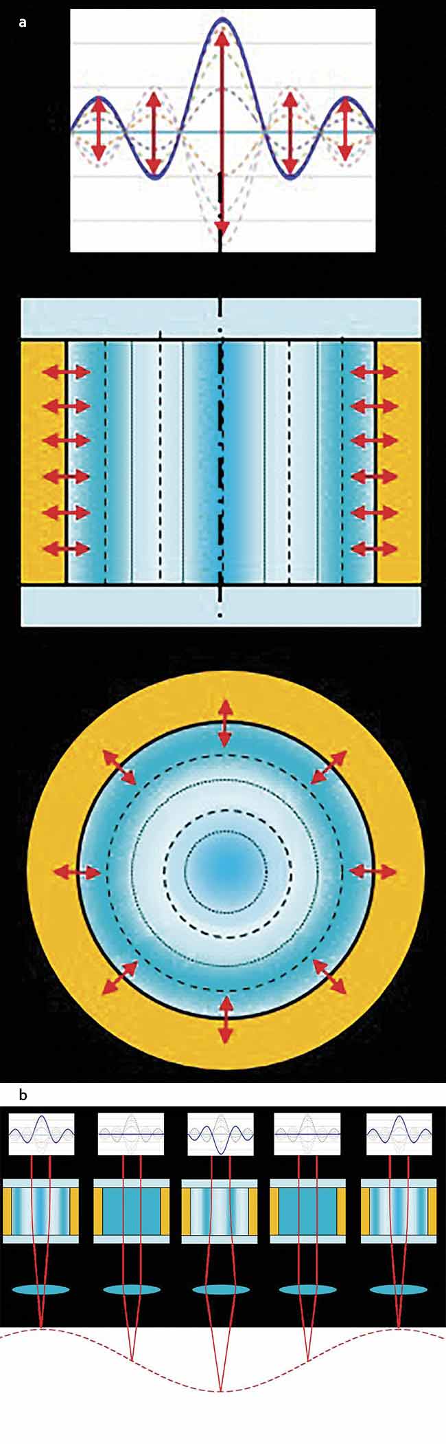
Figure 2. A TAG lens is formed by filling a cylindrical cavity with an optically transparent fluid. This type of lens samples all the focal lengths between the positive and negative extrema of the modulation (a). It can be combined with a microscope objective (b) or a different lens configuration, depending on the application. Courtesy of Mitutoyo.
The optical path length of light traveling through the lens medium is defined as:

Here n is the refractive index of the lens as a function of distance s along the path
C, and
OPL is the optical path length. In a standard glass lens, the refractive index is constant, and the mechanical curvature of the surface causes a change of the wavefront of the incident light, which results in bending, or focusing, of the incident light. Gradient index of refraction (GRIN) lenses can achieve the same focusing effect without any curved surfaces by using a refractive index as a function of distance that the light travels.
Now imagine a GRIN lens with a spatially and temporally tunable gradient index of refraction. This would allow for modulating the focal length of the lens as fast as the lens medium could be modulated. A TAG lens achieves this using sound waves. The acoustic excitation of the fluid medium leads to a standing
wave with a varying mass density in the body of the fluid, where the areas of higher density have a higher index of refraction. The oscillations of the mass density periodically change the index of refraction curvature following the shape of the acoustic drive. These peaks of the cycle define the optical lensing power of this technology. Figure 2 is a schematic representation of the lens driven by a sinusoidal acoustic drive.
At the peaks of the modulation, we get the maximum optical power, while in the midpoint between them the distribution of the refractive index is flat, which is the equivalent of no lensing in the fluid. In other words, within the period of the modulation, the lens samples all the focal lengths. The maximum optical power (inverse of the focal length) is proportional to the amplitude and the frequency of the modulation, as follows:
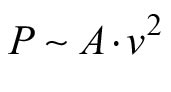
Where
A is the amplitude of the modulation,
ν is the frequency. So, the optical power of the lens can be controlled by changing the amplitude and/or the frequency of the driving acoustic wave. As the fluid and lens design parameters are fixed, the user of this technology has the option to modulate the amplitude and the frequency of the lens driver to get the optical power required by the application.
Typically, this lens technology operates between 50 and 500 KHz, depending on the choice of the fluid and the application. The clear aperture of the lens is determined by the drive frequency and increases with decreasing frequency. For example, the clear aperture of a lens operating at 70 KHz is around 11 mm.
Combining this type of tunable acoustic lens with large NA (numerical aperture) lenses, such as a microscope objective, enables the ability to maintain the extended focal range of the liquid lens and the high resolution of the objective lens. As such, this lens type has been proven to have a diffraction-limited optical performance. Therefore, the combination with other diffraction limited lens systems — with appropriate relay optics — does not influence the optical performance specifications. Such a combined benefit proves handy in designing a high-resolution microscope with a dramatically extended depth of field (DOF). For example, with a typical video microscope system, the DOF of the objective lens can be extended by more than a factor of 10 when combined with this type of lens technology, with little or no effect on the diffraction-limited performance of the microscope.
The ability of a TAG lens to sample all the focal lengths in the focus range provides an additional benefit. Using a continuous-wave illumination, it is possible to extract an all-in-focus 2D image of a 3D object. Another measurement mode is based on using a pulsed illumination
synchronized with this lens technology. This enables acquiring a stack of images from the measured planes along the height of the object, where each image corresponds to a specific value of the lens phase (i.e., a specific height) (Figure 3). The height measurement resolution (Z resolution) in this approach will be determined by the phase difference between the steps (the distance between the red and blue dots), as well as by the pulse width of the light source. In this mode of operation, it is possible to reconstruct the high-resolution 3D image of the object, where the resolution along the height of the object would be determined by the step size of the lens phase, while lateral resolution would be determined by the overall optical system.
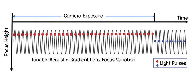
Figure 3. Measurement mode using a TAG lens synchronized with a pulsed light source for 3D inspection. An image can be taken for each lens phase, indicated by the position of the light pulse (red or blue dots) along the cycle of the lens (gray sinusoid). Within a camera exposure time, multiple lens cycles and light pulses with the same phase are acquired. The number of the cycles within the camera exposure can be tuned depending on the image’s signal-to-noise ratio. Courtesy of Mitutoyo.
Although a detailed model describing
the principles of the lens technology is outside the scope of this overview, it is important to note that the discussion above relates to the linear regime. In case of very large drive amplitudes or strong absorption by the liquid, the performance may no longer be linear. In such cases, a nonlinear model must be used to predict and describe the performance of this type of lens.
Applications
Diffraction-limited performance, fast focus variation, lack of mechanically moving parts, and transparency to visible and near-IR light make a TAG liquid lens a perfect fit for many industrial, scientific, and medical applications. Additionally, insensitivity to orientation enables liquid lenses to be used on various platforms, such as on robot arms. This adaptability is necessary in many vision measuring systems, inline inspections, and other applications.
The diffraction-limited performance opens the door for integrating this liquid lens into high-precision and high-accuracy metrology systems used in semiconductor, automotive, and aerospace applications. This allows for significant enhancements across multiple performance metrics of these systems, such as measurement throughput and imaging depth, also known as the Z-range. The high focus variation speed at or above 70 KHz rate, combined with high-speed imaging and image processing techniques — using field-programmable gate arrays, for example — enable performance enhancements for myriad measurement and inspection modalities. For instance, the combination of this liquid lens with high-speed embedded image processing enables increasing the measurement throughput of inspection systems, simplifying the interfaces, and minimizing the amount of hardware, thereby paving the way for faster and more economical inspection solutions.
In addition, the ease of integration with high-resolution microscopes and telecentric lenses provides practical solutions that address the traditional challenge of accomplishing high resolution combined with a large DOF (or a large field of view) in those devices. For example, by integrating a TAG lens with a high-resolution microscope, it is possible to obtain enhanced performance by maintaining high resolution on the one hand and extending the effective DOF on the other. Moreover, the ability to image the sample controllably at various heights by using a pulsed light source, synchronized with the liquid lens and the image acquisition system, allows for high-speed autofocus and 3D imaging without any mechanically moving parts. Such performance enhancements provide benefits in biomedical and industrial applications. Another example is combining the tunable acoustic gradient liquid lens with telecentric optical systems. In this modality, one can achieve a dramatically extended DOF that would not be easily achievable with conventional telecentric lenses. This allows for the inspection of large parts, or multiple planes separated by large distances, in industrial applications.
The combination of a TAG lens with
high-speed image acquisition and processing also enables high-speed 3D measurements and analysis. This capability provides new possibilities in 3D defect detection and 3D measurement of moving parts for inline inspection in production. With Industry 4.0 (IIoT) trends and the increased importance of 100% inspection
of parts in factories, TAG lenses are expected to become a ubiquitous tool for high-speed noncontact inspection and guarantee.
Finally, the transparency of a TAG lens to visible and near-IR light means it can be used in high-power laser applications, such as laser-material processing and multiphoton microscopy, with nanosecond or ultrafast near-IR lasers
6-9. The synchronization of the high-power laser with the liquid lens can enable controllable material processing in a bulk of the materials in laser engraving, drilling, and other laser-material processing applications
10.
Given the advancing speeds of CMOS cameras and embedded image processing, as well as pulsed light sources approaching the high speed of TAG lenses, it is expected that this lens technology will apply to an increasing number of applications in metrology and inspection of parts across a wide range of industries, including biomedical, semiconductors, aerospace, automotive, and defense.
Meet the authors
Vahan Senekerimyan is senior manager at Micro Encoder Inc., a subsidiary of Mitutoyo America Corp. He leads R&D and technology development for Mitutoyo’s advanced metrology and inspection solutions. Senekerimyan
is involved with the development and commercialization efforts of the TAG lens variable focus lens technology; email:
[email protected].
Paul Gladnick is a staff optical engineer
at Micro Encoder Inc. He is a leading developer of high-precision noncontact metrology systems. Gladnick has an in-depth knowledge and expertise in tactile and noncontact measurement technologies and their applications
in various industries.
Paul Nuara is an optical product specialist for Mitutoyo America Corp., supporting optics and optical measuring systems.
References
1. Parrot Drones SAS (2017). Corning Varioptic Variable Focus Liquid Lens product specification: MADS - 160214 - Arctic 39N0 family,
www.brilliantoptics.com/wp-content/uploads/2017/01/mads_-_160214_-_arctic_39n0_family.pdf.
2. M. Blum et al. (2012). Compact optical design solutions using focus tunable lenses. SPIE Optical Design and Engineering IV,
Proc SPIE, Vol. 8167.
3. Optotune (2019). Tunable Lens product specification: Fast Electrically Tunable Lens EL-10-30 Series,
www.optotune.com/images/products/Optotune%20EL-10-30.pdf.
4. E. McLeod et al. (2006). Multiscale Bessel beams generated by a tunable acoustic gradient index of refraction lens.
Opt Lett, Vol. 31, p. 3155.
5. E. McLeod and C.B. Arnold (2007).
Mechanics and refractive power optimization of tunable acoustic gradient lenses.
J App Phys, Vol. 102, p. 033104.
6. M. Duocastella and C.B. Arnold (2013).
J Phys D Appl Phys, Vol. 46, Issue 7, p. 075102.
7. X. Chen et al. (2016). Two-photon light-sheet nanoscopy by fluorescence fluctuation correlation analysis.
Nanoscale, Issue 19,
https://doi.org/10.1039/c6nr00324a.
8. W. Zong et al. (2015). Letter to the Editor, Large-field high-resolution two-photon
digital scanned light-sheet microscopy,
Nature, Cell Research, Vol. 25, pp. 254-257.
9. S. Piazza et al. (2017). Enhanced volumetric
imaging in 2-photon microscopy via acoustic lens beam shaping.
J Biophotonics,
Vol. 11, Issue 2,
https://doi.org/10.1002/jbio.201700050.
10. M. Duocastella and C.B. Arnold (2013).
App Phys Lett, Vol. 102, Issue 6, p. 061113.