Full company details
PI (Physik Instrumente) LP
Sub. of Physik Instrumente (PI) GmbH & Co. KG
Motion Control, Air Bearings, Piezo Mechanics
 16 Albert Street
Auburn, MA 01501
United States
Phone: +1 508-832-3456
Fax: +1 508-832-0506
Noncontact Metrology for Aspherical Lenses
Photonics Spectra
Jun 2020A new test method for aspherical lenses makes use of the precision and flexibility of a six-axis hexapod positioning stage.JÜRGEN SCHWEIZER, MAHR GMBH, DORIS KNAUER AND STEFAN VORNDRAN, PHYSIK INSTRUMENTE (PI)
Freeform and aspheric optics have
become popular because they provide better performance than traditional optics and can do so with fewer optical elements. The downside of the higher performance is increased complexity in design, manufacturing, and testing (Figure 1). For testing, noncontact interferometric methods that are based
on a parallel-kinematic (hexapod) six-
degree-of-freedom mechanism can position many types of optics in any orientation in space with submicron precision, with some methods achieving nanometer-level resolution. Compared to traditional, stacked, multiaxis positioning, hexapod motion systems offer greater flexibility and accuracy with higher stiffness and a user-programmable center of rotation or pivot point. Other advantages include a central aperture and lower susceptibility to accumulative, parasitic motion errors.
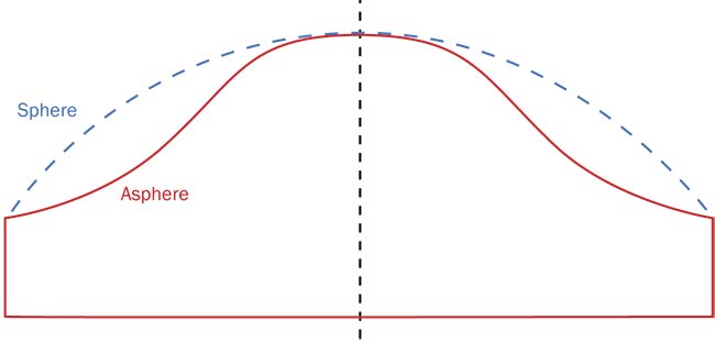
Figure 1. In a conventional spherical lens, the surface is equidistant to the central point. An aspheric surface deviates from the traditional spherical curvature and is harder to produce and test. Courtesy of PI.
Precision positioning with hexapods
Hexapods, also known as parallel kinematic machines or Stewart-Gough platforms (Figure 2), have long been used in precision positioning. In astronomical
telescopes, for example, they align secondary mirrors to the main reflectors. Hexapods have become better known recently with the ALMA Observatory telescope cluster’s successful imaging of a black hole. The cluster, which is located in the Atacama Desert in Chile, comprises dozens of telescopes spread over a large area and synchronized precisely to perform like a single large telescope. Each telescope in the cluster relies on hexapods to perfectly align its secondary reflectors with the main reflector.
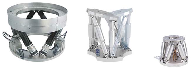
Figure 2. Hexapods vary in design and size. A large hexapod for astronomical telescopes has a 600-mm platform diameter and a 200-kg load capacity (left); a midsize hexapod (center) has a 300-mm platform diameter and a 50-kg load capacity; and a miniature hexapod (right) has a 100-mm platform diameter and a 5-kg load capacity. Courtesy of PI.
Parallel kinematics
Whether synchronizing large optics or measuring complex aspheres, the precise control of a parallel kinematic multiaxis motion system requires significantly more processing power as compared to a stack of individual single axes (Figure 3). Because all six actuators are involved, hexapod multiaxis systems require that thousands of complex matrix calculations be performed per second. This is true even if motion in only one geometric axis is executed, for example, a lateral move
in the y-coordinate. An additional layer
of complexity is added when actuators with cardanic joints and offset axes
necessary to achieve higher stiffness are used. In a traditional (serial kinematics) multiaxis motion system, the controller
can manage one axis at a time, and
coordinate transformation math is not
required. For reasons of cost and complexity, multiaxis hexapods with submicron precision were not commercially available for decades. However, with the advent of affordable high-performance microprocessors and the move toward smaller feature sizes in the optics, photonics, and semiconductor industries, the benefits now outweigh the complexity.
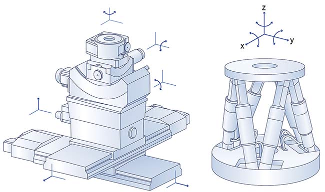
Figure 3. A conventional, serial, kinematic, multiaxis positioning system versus a parallel-kinematic hexapod. All actuators in the hexapod support the moving platform in parallel, directly, providing improved stiffness and multiaxis precision. Courtesy of PI.
In a conventional stack of single-axis positioning stages, each actuator is
assigned to exactly one degree of freedom and each position feedback sensor can measure only intended motion on the corresponding positioning axis. If, for example, commanded motion along the x-axis produces unwanted orthogonal
motion in the y-axis, the sensor on the
y-axis cannot detect it and the controller
cannot compensate for it. Therefore, any undesirable motion, whether based on guiding errors of individual axes or structural bending, cannot be detected or compensated.
In a parallel kinematic hexapod, the moving platform is controlled and
supported simultaneously by all six actuators in parallel, making the setup stiffer and more accurate. The moving mass is significantly reduced and evenly divided between all actuators, which results in higher dynamics, greater stability, and
a much higher resonant frequency responsible for suppressing excitation of unwanted vibrations. The symmetrical design also allows for the large, clear aperture necessary for transmitted light applications.
Rapid testing of aspherical lenses
High-precision asphere testing methods must be noncontact, fast, and flexible for high-volume production (Figure 4). Therefore, CGH (computer-generated holography) and classical stitching are ruled out. CGH-based methods lack flexibility and are economical only for large series production because the holograms must be created individually for each test object shape. Stitching techniques are time intensive because they require many individual interference patterns to be captured and calculated. A new interferometric technique called tilted wave interferometry (TWI) and invented by researchers at the Institute of Applied Optics at the University of Stuttgart, Germany, can bridge the gap and provide both flexibility and speed.
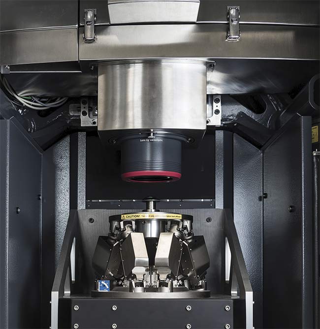
Figure 4. The entire surface of a small aspheric optic can be measured in less than 30 seconds
with the help of a miniature hexapod micropositioning system for calibrating and measuring.
This hexapod, shown in close-up, uses special actuators that combine long travel with a low profile. Courtesy of Mahr.
TWI principle of operation
TWI works in a way similar to conventional interferometry. However, TWI does not acquire complete object data in one single image but in several subapertures that are active at different times. In the case of aspheres and freeforms, which have relatively steep surfaces, acquiring the test object data in one pass would cause interference patterns to converge, making them impossible to resolve afterward. If the individual geometrically distributed subapertures are actively switched, different tilted wavefronts hit the inspection optics so that the resulting interference patterns do not overlap. At the end of the process, an undisturbed interference pattern of a local area of the test object surface is obtained from each subaperture (Figure 5). The interferometric data collection process only takes 20 to 30 seconds, and while the calculations are handled in the background, the measurement process of the next optics can already be started.
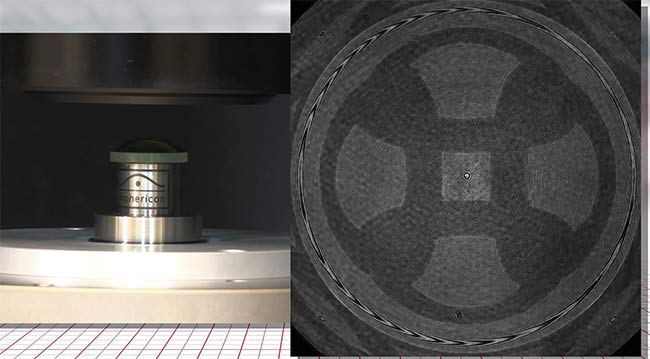
Figure 5. Undisturbed interference patterns of different subapertures for local parts of the test object surface.
Because all six actuators are involved, hexapod
multiaxis systems require that thousands of complex
matrix calculations
be performed per second. Courtesy of Mahr.
In addition to aspheres, freeform optics (geometries deviating from standard shapes) can also be measured. The robustness of concept allows setup directly in the production area. Subsequently, the individual interference patterns are combined into a single pattern. The final single pattern represents the surface of an (aspheric) test object and can then be evaluated accordingly.
Reference, calibrate, measure
The TWI system needs to be referenced and calibrated like every other measuring device. For this purpose, a sphere manufactured according to highly accurate and known geometrical specifications is moved for each subaperture to various positions in the measuring volume. In this process, the sphere’s surface is measured with the respective subaperture. Finally, the individual measurements are evaluated and a correction algorithm is created for each subaperture. For TWI to provide reliable results, a highly precise five-axis positioning mechanism is required. The calibration process needs to cover the complete measuring volume, requiring a large number of positions in the measuring volume to be approached. Since lateral position errors of the calibration sphere directly affect the correction algorithm of the respective subaperture, the calibration sphere needs to be positioned exactly and its position must be kept stable during measuring. Each position must be approached with a repeatability of better than 0.5 µm and accuracy of 5 µm.
During the actual measuring process, the hexapods have to provide stable positioning of the test object in five degrees of freedom. Both the commanded (desired) and actual position need to be matched exactly. For example, tilt errors may not exceed 60 µrad.
Currently available hexapods suitable for TWI or other optics- and photonics-related applications provide resolution down to 10 nm and below. Linear motion ranges between 35 and 100 mm and rotation ranges between 40° and 60°. Typically, the six hexapod struts (legs) are based on precision ball or roller screws, driven by brushless DC motors. For higher-speed and higher-bandwidth applications, voice-coil-driven hexapods are used. Hexapods require a specific controller to handle the inverse kinematics coordinate transformations. All this is transparent to the user, and motion commands are specified in Cartesian coordinates, while the controller takes care of the path planning
and precise positioning commands to each of the six individual actuators. A very useful feature for any alignment
application is the user-programmable pivot point or center of rotation. Integration into higher-level control systems is facilitated by the open EtherCAT interface standard.
Meet the authors
Jürgen Schweizer, Ph.D., is a product manager at Mahr GmbH in Göttingen, Germany.
He has a doctorate in control engineering, has participated in more than 10 patents, and has managed various projects in optical materials processing and measuring instruments; email:
[email protected].
Doris Knauer is project manager for global marketing campaigns at Physik Instrumente (PI). She is responsible for worldwide communication of strategic marketing topics in
the field of industrial automation. Knauer has
a diploma in geography from Heidelberg
University; email:
[email protected].
Stefan Vorndran is vice president of marketing at PI USA. He has a degree in electrical engineering from the University of Darmstadt, Germany; email:
[email protected].