Full company details
Photon Engineering LLC
 310 S Williams Blvd.
Suite 222
Tucson, AZ 85711
United States
Minimizing Stray Light in Everyday Optical Systems
Photonics Spectra
Aug 2018Stray light affects virtually every fabricated optomechanical system and can be controlled best when considered early.RICHARD PFISTERER, PHOTON ENGINEERING LLC
Very often when optical engineers hear “stray light” or see a requirement for some level of either stray light analysis or testing, they become concerned. They wonder how such a simple system can have stray light problems. Or they think stray light problems are solely the concern of big aerospace projects. In fact, virtually every optomechanical system has stray light issues of some type or another — the severity depends on the ultimate application.
Controlling stray light is not an afterthought; it must be considered as early in the design process as possible because the number of viable options for controlling it diminishes as the project matures.
Unfortunately, systems engineers and lens designers generally consider only idealized performance when baselining system capabilities since these calculations are readily available within all major optical design software. The mechanical implementation of the system usually follows the optical design. It is difficult to do optical and mechanical design concurrently, so the information required to perform a complete stray light analysis is rarely available early in the design cycle. However, the awareness of ubiquitous stray light mechanisms and physical limitations, as well as good stray light control practices, can go a long way in preventing serious problems later in the project development.
Origins of stray light
Many engineers mistakenly believe that all stray light problems are due to poor implementation of the baffles and other structural components. Implementation can certainly be part of the problem, but it does not bear all of the blame. Limitations imposed by physics play a significant role in many applications. For example, in astronomy, diffraction effects from the aperture and secondary mirror supports can mask the visibility of a planet circling close to its parent star. In thermal systems, the thermal self-emission of the imaging hardware can compete with the thermal signature of the target, rendering the latter nearly invisible. Microroughness left over from the fabrication process of lenses and mirrors generates a scatter field that extends over the area of the detector. Physical and chemical processes limit just how “black” a black paint can be.
The environment itself can be the cause of stray light problems. For example, particulates present in the environment deposit onto optical and mechanical surfaces over time, and these can significantly increase the scatter produced by the surfaces. Even though cleaning can be an option under some circumstances, as during integration and test in a controlled environment, this is typically impossible to perform in many applications, such as on spacecraft.
However, cleaning is not a panacea: Small particles are held onto a surface by van der Waals forces and consequently very difficult to remove. Furthermore, cleaning risks damaging the surface, which is why telescope mirrors in large observatories are cleaned only infrequently — hence the adage, “A dirty mirror performs better than a poorly cleaned one.”
Another environmental stray light mechanism is nonvolatile residue (NVR). NVR is what is left on the surface when materials such as solvents, oils, paints, plastics, and glues evaporate or outgas over time. This is more common than people realize. In hot climates, a thin hazy film develops over time on the internal windshield of a car because of outgassing of the plastic components in the dashboard.
Even with software and hardware advances, the race between model complexity and ray trace continues.
Unfortunately, much of what we know about NVR in aerospace applications is anecdotal. It is poorly characterized because of large variations in the types of molecular species present and deposition scenarios, to say nothing of the difficulties associated with actually measuring the levels of outgassing on the surfaces. However, NVR can have three significant effects on an optical system mounted on a spacecraft: (
1) It can reduce the transmission by polymerization of the organic constituents because it acts like another thin film layer; (
2) it can change the scatter properties of a coating; and (
3) in the case of a multilayer coating, it can detune the original’s response coating.
The limitations imposed by physics and the environment are largely insurmountable, but engineers can have a major influence on stray light levels through careful consideration of the hardware implementation.
Lens designers can choose to implement an optical system with field and Lyot stops, which have been shown to be effective at controlling out-of-field stray light. During optimization, designers also can take advantage of controls available in modern lens design software to minimize the effects of ghost images.
Modern optical engineering software — essentially CAD software with extensive bidirectional scatter distribution function (BSDF) — along with modeling, nonsequential ray tracing, and book-keeping capabilities, make it possible to determine which structure(s) are responsible for which stray light artifact(s) present on the detector. This knowledge can often lead to implementation changes that result in lesser amounts of stray light. In the stray light literature, it is recognized that the most effective ways to control implementation-related stray light is by moving it or blocking it. With BSDF data readily available in the open (publicly accessible) literature, from vendors and measurement labs, analysts can perform “what if” experiments in software to determine the best paint(s) or other surface treatment(s) to minimize stray light in a system.
Astronomy
Whether or not we are alone in the universe is one of the most important questions humans have ever pondered. Since the first confirmed detection of an exoplanet in 1992, astronomers have been designing and launching increasingly more sophisticated spacecraft to look for planets circling stars, hoping to find one capable of harboring life
1.
But the problem of detecting a dim object circling a much brighter star is not trivial. Diffraction from the aperture function, which includes the outer aperture of the telescope, as well as the central obscuration and secondary support struts in a reflecting configuration, can hide the signature of the dim object.
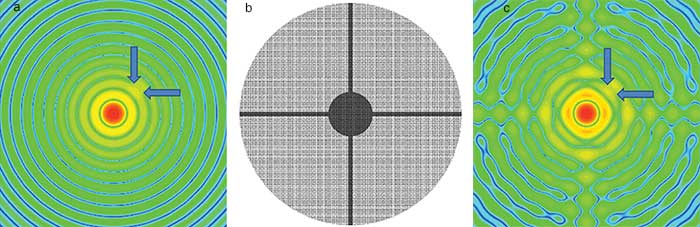
Figure 1. Diffraction pattern formed by a 10th magnitude star and a 25th magnitude planet (a); central obscuration and strut geometry (b); and diffraction pattern of stars including the effect of obscuration diffraction (c).
For example, consider a 10th magnitude star with a 25th magnitude planet circling, as seen from Earth, 0.1 arcsec away (Figure 1). Excluding the central obscuration and struts for a moment, the planet is positioned very close to the 16th diffraction ring, making it quite difficult to detect. Adding the obscurations only complicates the diffraction pattern, and, if the planet were positioned along one of the axes of the strut diffraction, it would be almost impossible to resolve.
Photography
Completing the lens design is only one of the first steps in the development of a sensor system. To perform as designed, the elements must be precisely held with respect to each other, which is typically done in a handoff to the mechanical designer. However, most mechanical designers do not have the experience or software tools to assess the effect of various paints and/or surface treatments on the stray light characteristics of the system. This can lead to undesirable stray light artifacts.
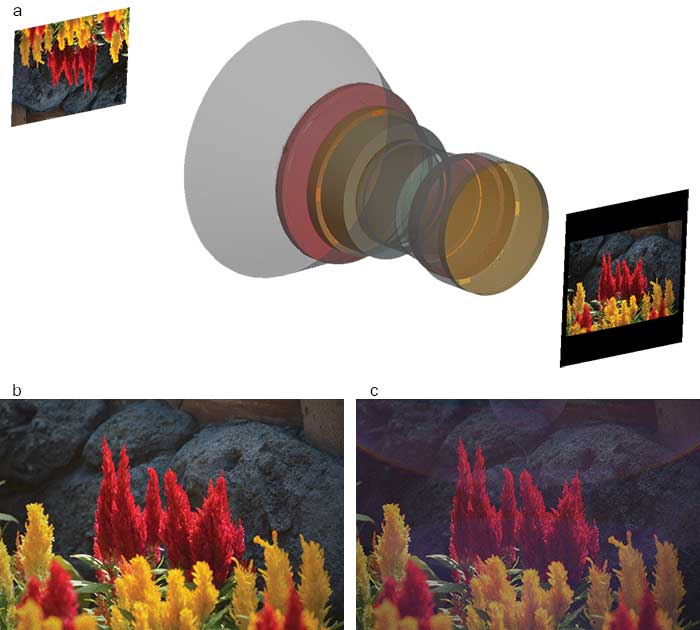
Figure 2. Imaging a scene through a double-Gauss lens (a); ideal image (b); and image showing effects of reflections from internal baffle surfaces (c).
Figure 2 shows a conventional double-Gauss lens mounted in a barrel assembly with a short sunshade implemented as a baffle. The interior surfaces of the baffles are black-anodized, which is visually attractive because it is shiny. But it’s a poor choice from a stray light standpoint because it also has reflective (specular) properties. If the scene is back-illuminated by the sun at some relatively acute angle — 35° in this case — the interior barrel surfaces can reflect the incident sunlight and create stray light artifacts on the image and thus an overall loss in contrast.
Thermal imagery
Traditionally, thermal imaging systems working in the 8- to 12-µm spectral band were used exclusively by the aerospace and defense industries to image targets obscured by clouds, dust, etc. However, more recently, medical device developers have realized the power of thermal imagery to detect breast cancer, skin cancer, and other diseases by processing very slight temperature differences present in the thermal images.
In truth, the problem is actually considerably more complex because there are multiple sources of thermal power to consider: the intended target, the background, and the thermal imaging system itself. Usually, the target and the background are given by the mission scenario and are considered together. But unless the imaging system is cooled to reduce its thermal self-emission, it will also contribute to the signal on the detector, and there will be a net reduction of contrast or loss in signal-to-noise ratio.
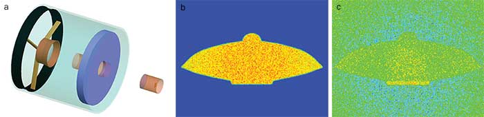
Figure 3. Diagram of a thermal imaging telescope (a); ideal thermal image of a UFO (b); and thermal image showing effects of self-emission from a telescope (c).
Figure 3 shows an example of a thermal imaging sensor — in this case a Cassegrain telescope with gold-coated optical surfaces and black internal baffles — imaging a UFO located a long distance away from the sensor. Ignoring the thermal contribution from the sensor for a moment, the thermal image of the UFO is very high-contrast and readily discernable.
Pristine gold coatings typically have reflectances on the order of 98 to 99 percent and hence emissivities of 0.01 to 0.02. If the gold mirrors are degraded from particulate contamination, such that their effective emissivities rise to 0.05, then the composite thermal image is substantially degraded.
Laser send/receive systems
Laser send/receive systems can be complex optomechanical systems with numerous coaligned optical paths and elements, leading to all sorts of unintended (stray) optical paths. Unless the company developing the system has paid careful attention to pathological ghost paths (and there could be hundreds or thousands of paths depending on the overall complexity of the system), it could be surprised to find that optical elements are shattered during operation because of high imaged fluence levels.
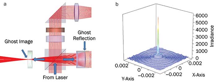
Figure 4. Section of laser send/receive system with a severe ghost problem (a); a focused ghost produces large irradiance on surface of lens (b).
A laser send/receive system can have a particular bad ghost-reflection problem: One of the optical elements in the laser path produces a ghost reflection that comes to focus on a surface of an element in the common transmit/receive path (Figure 4). Since the YAG lasers commonly used in these systems have enough coherence over short distances, it is entirely possible that a ghost reflection could have enough power to blow out an optical element.
Calculations made accessible
Optomechanical systems come in a nearly infinite variety of configurations, but just about all of them have two elements in common: They have at least one optical surface (e.g., a mirror or front surface of a lens), and they have some sort of baffle in front of the optical surface. This could be considered a “degenerate” optomechanical system. Such a system would only have two (or possibly three, if aperture diffraction is included) stray light mechanisms: first-level scatter from the optical surface to the detector and second-level scatter from the baffle to the optical surface to the detector. Certainly, any real complex system will have many more stray light mechanisms present and therefore higher stray light levels, so this system can be considered a truly best-case scenario.
From analyses of numerous systems, researcher Alan Greynolds recognized this “degenerate” configuration and published the equations for the stray light levels for what he called a “well-baffled” system
2. Though wildly optimistic, this approach is very useful for baselining the performance of a system very early in the conceptual phase.
Performing accurate stray light calculations in a physical system is quite a bit more complicated than it first appears, largely because of the sheer volume of information that must be consolidated into the model. Most optical engineering software can readily import lens prescriptions and structures built from CAD programs.
Optical surface microroughnesses and volume scatter properties must be either estimated or measured. The transmission, reflection, and polarization properties of optical coatings must be characterized and reduced to tables of data or functional forms, as required.
Scatter properties of paints and other surface treatments must be characterized and formulated as BSDF functions, a process that could involve approximations or curve fitting.
Fortunately, nature seems to prefer only five different functional forms for BSDF, so parametric models may be used effectively
3.
Often, the properties of the environment must be taken into account; these include temperature (for thermal calculations), distribution of particulates in the air, and molecular species of solvents, paints, and lubricants (as NVR sources). Developing the model to the level of fidelity required for accurate stray light calculations can take months, particularly if any significant iteration is required for the facilities performing measurements.
Constructing the model is just the first step. Stray light calculations themselves can take hours, days, weeks, or longer, depending on model complexity, type of stray light calculation being performed, and available computer resources. With ever-increasing complexity and the desire to model everything down to screw heads and fillets, runtimes are becoming prohibitive.
This computational burden is problematic when rapid decisions must be made during the development process. Consequently, optical software vendors are investigating several options, ranging from cloud computing, to distributed computing on networks and clusters, to the utilization of GPUs (commonly used in the movie industry for rendering).
And these are not significantly different from stray light analysis. Even with software and hardware advances, the race between model complexity and ray trace continues.
Balancing act
System complexity is no indication of the potential magnitude of stray light problems. In fact, some very complex optomechanical systems have very low stray light levels precisely because they are complex. In a design environment where “doing more with less” is the mantra, it is frequently impossible to find a physically realizable system configuration that can meet system performance requirements.
Albert Einstein was not known as a stray light analyst, but his words are particularly relevant to baffle design and stray light control: “Everything should be made as simple as possible, but not simpler.”
Meet the author
Richard Pfisterer is president and co-founder of Photon Engineering LLC and is regarded as one of the world’s leading authorities on scatter theory/measurement and stray light analysis. He holds bachelor’s and master’s degrees in optical engineering from the University of Rochester; email:
[email protected].
References
1. A. Wolszczan and D.A. Frail (1992). A planetary system around the millisecond pulsar PSR1257 + 12.
Nature, Vol. 355, Issue 6356, pp. 145-147.
2. A. Greynolds (1981). Formulas for estimating stray-radiation levels in well-baffled optical systems.
Proc SPIE, Vol. 257, Radiation Scattering in Optical Systems.
3. R. Pfisterer (2018). Scatter and BSDF measurements: theory and practice, in
Photonics Buyer’s Guide 2018. Pittsfield, Mass.: Laurin Publishing, pp. H67-H70.