Full company details
PCO-TECH Inc.
Sub. of Excelitas PCO GmbH
 1000 N West St., Suite 1200
Wilmington, DE 19801
United States
Being a Camera User - Do You Need a Large Dynamic Range?
The “dynamic” or “dynamic range” of an image sensor or a camera system is a widely used term to characterize the ability of a camera system to measure and distinguish different levels of light. The correct expression for it is “intra-scene dynamic” or “intra-scene dynamic range”, but usually camera manufacturers just refer to “dynamic” or “dynamic range” in their technical data sheets and advertisements. In the field of photography, the dynamic range is analogous to the contrast range. However, many camera manufacturers define dynamic range from a different point of view. For that reason a distinction should be made, between the “dynamic range of a sCMOS, CMOS or CCD image sensor”, “dynamic range of an analog-to-digital-conversion”, “usable dynamic range” and “maximum dynamic range or maximum SNR”.
1. Benefit for a Camera User
What is the benefit of a large dynamic or dynamic range of an image sensor or a camera system? All displays and TV screens are in 8 bit dynamic, because the un-trained eye is only able to distinguish approximately 256 light levels. Radiologists are trained to see more, therefore their screens go up to 10 bit. The general perception could be that people might say 8 bit is far good enough. This is further supported by the fact that nowadays people are very happy with the 8 or 6 bit dynamic range of their smartphone cameras because they deliver nice and colorful pictures, so the question remains, what is the advantage of a large dynamic range?
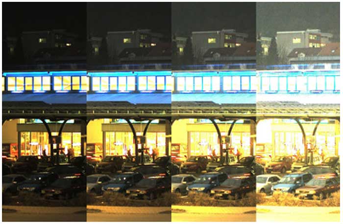
Four extracts of the same night image, which was taken in the evening out of the lab towards a supermarket in Kelheim with a pco.edge 5.5 color sCMOS camera system. The difference between each column is the way the 16 bit image was scaled to the 8 bit world of the print or the screen, but all versions have been created of the same raw data file. The first column on the left side shows a full scale conversion (value 65536 (16 bit max) -> value 256 (8 bit max) and value 0 (16 bit) -> value 0 (8 bit)), while the column on the right shows a low scale conversion (value 1024 (16 bit low) -> value 256 (8 bit max) and value 0 (16 bit) -> value 0 (8 bit)). The other columns show different conversions in between.
The answer is more information. A higher intra-scene dynamic range corresponds to a larger amount of light levels which can be detected and distinguished. How can this be perceived or used? Have a look at the 4 images in figure 1. The extracts in the four columns have been generated from the same 16 bit raw image taken with a pco.edge 5.5 color sCMOS camera. The original image was exposed in a way that the bright lights of the supermarket at night did not overexpose, which can be seen from the full range conversion from 16 to 8 bit. Therefore the full amount of information is present in the raw data but cannot be observed in this version of the image. From left to right now the conversion range is minimized, revealing from column to column more details (more information) in the darker areas of the image. Until the right column where the conversion is down to the low light range, generating “overexposed” areas (due to the conversion) but also allowing to distinguish tiny details formerly hidden in the shadows. This is one option to look at more information due to a higher dynamic (range). And for some applications like high quality 3D measurements, if non-cooperative (highly reflecting) surfaces are involved, it is prerequisite.
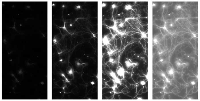
Four extracts of the same fluorescent image of a Calcium indicator in neurons, which was taken with a pco.edge 5.5 sCMOS camera system. The total image was not full scale illuminated as can be seen in the left column, which shows a full scale conversion (value 65536 (16 bit max) -> value 256 (8 bit max) and value 0 (16 bit) -> value 0 (8 bit)). The second of the left columns shows a conversion which scales the maximum signal in the image to the maximum of 8 bit, the fluorescence can be seen, but some of the connections remain in the dark. The third column has a low scale conversion, now the connections can be well identified but some areas seem overexposed and don’t show structural information therefore. The final column applies a non-linear conversion which allows to display most of the structural information in the 8 bit world of the screen or the print.
Another approach to that issue is shown in figure 2. The original raw data were a fluorescence image of a Calcium indicator experiment in neurons taken with a pco.edge 5.5 sCMOS camera. Here the image was not fully exposed, as can be seen from the first column on the left side which shows a full scale conversion, resulting in a dark image. The next column was converted to the maximum signals in the image, where some structures are visible but the connections between the neurons can hardly be seen. If the conversion is lowered in the third column, the connections can be seen but the neurons are “overexposed” by conversion. To overcome this in the fourth column a non-linear conversion is shown, which allows the analysis of the structure.
In commercial raw shooter applications of photo cameras a higher dynamic allows to adjust the 8 bit final output photo in an optimum way that structures can be seen both in the shadows and in the light, if the camera provides such a dynamic range.
2. Dynamic Range of a Digital Image Sensor
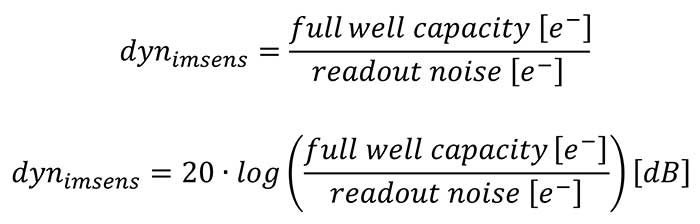
The dynamic range (dyn
imsens) is defined as the ratio of the maximum possible signal (which is in most cases identical or near to the “full well capacity” describing the maximum number of charge carriers a pixel can generate and collect), versus the total read- out noise signal
1 (in the dark). The data is either dimensionless and expressed as a ratio or expressed in decibels [dB]:
 1. The dark current contribution has been neglected for the considerations, because In most applications it is only relevant for very long exposure times.
2. All numbers are minimum requirements. If the quantization noise of the A/D Converters is considered and included to all calculations another bit has to be added.
Upon examination of the dynamic range values in table 1 and in case the full dynamic range should be made accessible to the user of a camera system, the ICX285 CCD image sensor should be digitized using 4096 steps (corresponds to 12 bit A/D resolution), the IMX174 CMOS image sensor should be digitized using 8192 steps (corresponds to 13 bit A/D resolution), the CMV4000 CMOS image sensor should be digitized using 1024 steps (corresponds to 10 bit A/D resolution) and the CIS2020A sCMOS image sensor should be digitized using 65536 steps (corresponds to 16 bit A/D resolution).
In case the full dynamic range of the image sensor is available to the user, it is clear that an additional gain is not meaningful because it does not provide extra information. In contrary the use of such a gain would reduce the usable dynamic range, since the change from one light level to the next would just cause a larger step in the digital signal and it would finally cause a saturation of the image values at a much lower light level. Therefore the use of an additional gain only helps, if the dynamic range of the A/D-converter is smaller than the dynamic range of the image sensor.
For example, the IMX174 would benefit from a 13 bit A/D conversion but the image sensor is just supplied with a 12 bit output. In this case, the adjustment of the gain allows the user to position the A/D range in a way such that it is either optimum for the lower or the higher end of the range of light levels. A different example is given by the CMV4000, where the user can select to read out either 8 – 10 – 12 bit values with an impact on frame rate and amount of data. Clearly the 12 bit readout for a 10 bit dynamic range image sensor does give higher resolved noise values, but does not give more information, since the dynamic range is just about 10 bit.
3. Digitization or A/D Conversion Dynamic Range
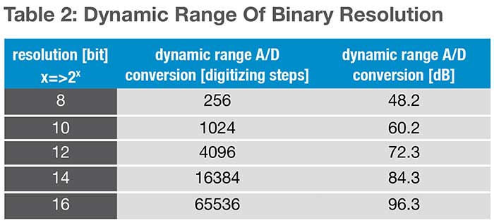
Generated charge carriers are usually converted into voltage signals through an optimized readout circuit (for CCD image sensors at the end of the readout registers and for CMOS image sensors in each pixel and at the end of the columns). These signals are amplified and finally digitized by an analog-to-digital (A/D) converter. Thus, the light signals (photons) are converted into digital values. The analog-to-digital converters have their own given resolution or dynamic range, that in most cases is presented as a power of the base 2, (2
x). This means that an 8 bit resolution corresponds to 256 steps or levels, which can be used to subdivide or convert the full scale voltage signal.
Camera manufacturers usually optimize a combination of the dynamic range of the corresponding image sensor, gain and conversion factor (defined as average conversion ratio that takes x electrons to generate one count or digital number in the image) to match the dynamic range of the image sensor with the dynamic range of A/D converter. In case the dynamic range value of the A/D converter is larger than the dynamic range of the image sensor (see 12 bit read- out data of the CMV4000 in table 1) often the camera manufacturers tend to give the A/D converter value as dynamic range value in their technical data sheets, which can be misleading. Therefore it is good to keep in mind that the dynamic range of the digitization is not necessarily identical to the usable dynamic range.
The resolutions above directly correspond to the theoretical maximum limit of the converter devices. Analog-to-digital converters have an average conversion uncertainty of 0.4 - 0.7 bit, which reduces the resolution for practical applications by approximately 1 bit. If the camera system is not limited in its dynamic range by A/D converter discrepancies, it is useful to inflate the A/D converter resolution by 1 or 2 bits. This is achieved by electronically adding a minor amount to the signal a so-called offset signal, so that the lower limit is solely provided via the image sensor and read out amplifier noise, with some resolution sacrifices from the converter.
4. Maximum SNR or Dynamic of a Pixel
Sometimes people analyze the technical data of an image sensor and look to the capabilities of a single pixel. For the image quality and the performance of each pixel the critical parameter is the signal-to- noise-ratio (SNR), because the larger it is the better the image quality is.
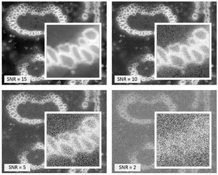
Four versions of a fluorescence image of a convallaria slice with different signal-to-noise-ratio settings (SNR = 15 – 10 – 5 – 2) to illustrate the influence on the image quality. The white framed images in the image show a zoomed part of the total image to overcome the “low pass” filter effect if the total image is reproduced at a lower resolution.
In figure 3 the impact of different signal-to-noise-ratios is shown, ranging from 15 – 10 – 5 – 2. Since the eye is very sensitive to structures in each image the same part is zoomed up to show the noise influence. For example at SNR = 2. Although the eye and our brain are still able to see clearly the convallaria slice structure in the noisy image, it is nearly impossible to determine the structures by means of image processing, since the image is too noisy.
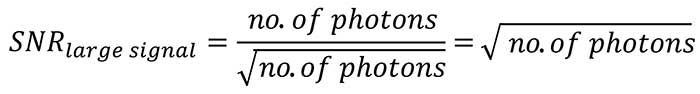
From physics it is known that in the low light range the SNR is strongly influenced by the total readout noise of the image sensor and the camera, therefore if the application is supposed to be in that range, it is important to have a very low readout noise. The larger the light signal becomes, the more the read- out noise of the camera becomes negligible and the noise behavior of the light signal itself becomes dominant. The photon or shot noise cannot be changed since it is related to the nature and physics of light. It corresponds to the square root of the number of photons. This in turn means that the SNR as ratio of the number of photons divided by the square root of the number of photons itself finally corresponds to the square root of the number of photons.
An implication of this consideration is, in case the SNR
max should be improved there are basically two pathways.
Either the image sensor is capable to collect as much light as possible (large fullwell capacity) or it is insensitive, such that a lot of light has to be collected to generate a good image (which agrees with experience from the former times of slide and negative films, where the most insensitive films for example at 50 ASA, required the most light to be collected and delivered the best image quality).
Furthermore it means that the maximum SNR in each pixel corresponds to the square root of the fullwell ca pacity of the pixel (see table 1):
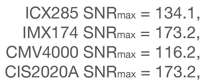
This is sometimes taken as maximum “dynamic” of a pixel, which is a lot smaller than the intra-scene dynamic range or dynamic range of the image sensor. But there are only few applications which suffer from the requirement to achieve the maximum SNR because they have too much light.