M. Kelnberger, InnoLas GmbH; G. Schwitzgebel, Universität Mainz
Particle image velocimetry (PIV) is an experimental tool in fluid mechanics and aerodynamics. The basic principle involves photographic recording of the motion of microscopic particles that follow the fluid or gas flow. Image processing methods are then used to determine the particle motion, and hence the flow velocity, from the photographic recordings. Provided there are enough particles within the area of flow under investigation, the entire velocity field of the flow can be determined.
The near-instantaneous velocity field is of particular importance. PIV therefore has all the advantages of a flow visualization method, but it can also provide valuable quantitative information. Once the velocity field is known, data such as vorticity and strain are easily obtained, and if there are sufficient PIV recordings, even the turbulence intensity can be estimated.
By helping to understand unsteady flow phenomena, PIV is quite useful in modern aerodynamics. Examples include aircraft wake (measurement of the wake vortices of a lifting aircraft wing); helicopter aerodynamics (investigation of rotor aerodynamics with respect to noise emission of various noise sources such as blade/vortex interactions); and transonic flow over airfoils.
In addition to studies in aerodynamics, PIV is increasingly used in the investigation of liquid flows (vortex-free-surface interaction, thermal convection and Couette flow between concentric spheres).
Interest is growing in aircraft wake studies because of increased airport capacities and the resultant takeoff and landing frequencies. Research projects on wake vortices using PIV techniques are driven by aeronautical research organizations and by the aircraft manufacturers. The subject of wake vortices is important for the efficiency of airports, since a reduction of wake vortices could lead to the reduction of the required distance between aircrafts and therefore increase the start and landing frequencies.
Research is also driven by safety considerations following several aircraft mishaps that were caused by wake vortex effects. For realistic investigation and meaningful results on aircraft aerodynamics, the use of cryogenic wind tunnels and nonintrusive optical flow measurement techniques like PIV are of increasing importance.
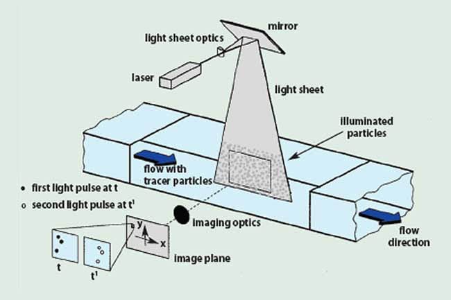
Figure 1. Experimental arrangement for PIV in a wind tunnel.
Basic principles
The experimental setup of a PIV system consists of several subsystems: a flow-producing facility like a wind tunnel with its possible subsystems (e.g., an injection system to cool down the gas and an exhaust system to control the tunnel pressure). In most applications, tracer particles have to be added to the flow. These particles have to be illuminated in a plane of the flow at least twice within a short time interval. The light scattered by the illuminated particles has to be recorded with a high-quality lens either on a single photographic negative or on two separate frames on a special cross-correlation CCD sensor (Figure 1).
The local displacement vector of the images of the tracer particles of the first and second illumination is determined for each area of the interrogation plane through statistical methods (Figure 2). In order to handle the amount of data that can be collected with PIV, sophisticated postprocessing is required. Therefore, the photographic PIV recording is digitized after development by scanners. The output of the CCD sensor is stored directly in real time in PC memory.
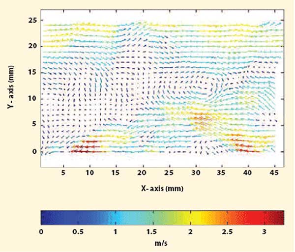
Figure 2. Velocity vector map from PIV postprocessing.
For a better understanding of the special technical solution in the field of laser illumination, some general aspects of the technique have to be understood:
Velocity lag: The need to employ tracer particles for the measurement of the flow velocity requires checking each experiment carefully as to whether the particle will faithfully follow the motion of the flow. Experience shows that small particles will follow the flow better even in high-speed air flows.
Illumination: For applications in gas flows, a high-power light source is required so that the light scattered by the tracer particles will expose the photographic film or the video sensor. A more powerful light source (e.g., a high-energy laser pulse) will allow the use of smaller tracer particles and minimize the problem of velocity lag.
Duration of illumination pulse: The duration of the illumination pulse must be sufficiently short so that the motion of the particles is "frozen" during the pulse exposure to avoid blurring the images.
Time delay between illumination pulses: Time delay between the illumination pulses has to be long enough to enable the displacement between the images of the tracer particles to be determined with sufficient resolution, and short enough to avoid particles with an out-of-plane velocity component leaving the light sheet between subsequent illuminations.
Laser technique and development
Developments in PIV over the past two decades have been influenced by the replacement of analog recording and evaluation techniques by digital techniques. Meanwhile, faster computer processor speeds and memories have improved the handling of complete digital PIV recordings by a personal computer. And progressive scan video cameras allow users to store the images of the tracer particles on separate frames for each illumination with a resolution of 1040 × 1320 pixels — a quality equivalent to evaluation of 35 mm photographic films in the past.
In addition to the use of digital recording and evaluation techniques, the development of reliable high-power laser sources influenced the improvement of PIV and its application in air flows. The required high-energy light pulse for high-speed air flow PIV (as used in the investigation of aircraft aerodynamics) was first made possible by the use of semiconductor lasers. Commercially available Nd:YAG lasers offer sufficient pulse energies from about 100 to 750 mJ. A further advantage of laser sources is their monochromatic light, which can be bundled into thin light sheets for illuminating and recording the tracer particles without chromatic aberrations. For PIV, the fundamental wavelength of 1064 nm is frequency-doubled to a wavelength of 564 nm in visible light.
Problems and limitations
While the required pulse energy for illumination is easily obtained by Nd:YAG lasers, the supply of two light pulses with a well-defined and appropriate time delay causes considerable technical difficulties. To enable the user to adjust the separation time between the two illuminations corresponding to the application and independent of the pulse strength, PIV lasers are mostly designed as double oscillator systems. The two lasers are triggered with a predetermined delay. Their pulsed beams are orthogonally polarized and are led to the common output aperture by an optical system of mirrors, polarizers, etc.
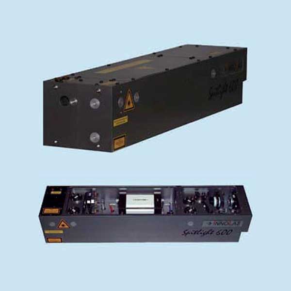
Figure 3. The InnoLas SpitLight system.
The main problem is an appropriate alignment of the two beams. A maximum colinearity of the two beams has to be realized. Yet, the beam profile of high-power Nd:YAG lasers tends to be rather poor. Hot spots and different ring modes are often found. Since a good beam profile — in the near- and far-field, and a mid-field distance of 2 to 10 m from the laser — is absolutely essential for PIV, the tuning of each individual laser and the adjustment of the optical system requires a maximum of specialized know-how, which makes PIV laser installation very expensive.
To address this problem, InnoLas has developed the YAGMaster double-pulse laser system with pulse energies from 100 to 450 mJ at a laser wavelength of 532 nm. Our goal was the generation of a double pulse with a time difference of 1 to 200 µs from a single oscillator. This is done by refiring the oscillator cell during the pulse emission. This eliminates the need for the complicated and costly superposition of two separate beams commonly applied. The beam profile (flat top) ensures uniform illumination and, because of the single-oscillator method, is completely identical for both beam pulses.
Application at the DLR
The efficiency of the system has been demonstrated with a pilot application at the Deutsches Zentrum für Luft- und Raumfahrt (DLR), the German Aerospace Center in Göttingen, Germany. At the DLR, cryogenic investigations of the trailing vortices of large future transport aircraft have been performed on an aircraft half-model with different wing tip devices. The model has been installed in the cryogenic wind tunnel of the German-Dutch wind tunnels (DNW) in Cologne, Germany. PIV measurements were carried out at airflow velocities of approximately 50 m/s and temperatures of less than –170 °C with particle sizes less than 1 µm.
In the DLR tests, a single-oscillator Nd:YAG double-pulse laser from InnoLas was used for illumination. This new design made it possible to generate two light pulses with a defined time delay from one laser source. The two resulting beams have an excellent spatial intensity profile, which is identical for both pulses and perfectly overlapping for pulse separation times between 1 and 200 µs. The output energy was 2 × 120 mJ. This energy was sufficient to illuminate the chosen recording plane. The time delay between the two laser pulses was set between 7 and 20 µs. The size of the observation area was approximately 80 × 110 mm. The light sheet thickness was adjusted to about 1.5 mm. The sheet was oriented normal to the main flow direction 0.15 m behind the wing tip device. A CCD camera with a spatial resolution of 1040 × 1320 pixels was used as the recording device.
With the new single-oscillator double-pulse laser method, the technical requirements for PIV measurements in high-speed air flows with small tracer particles — high pulse energy, well-defined and appropriate time delay between the laser pulses and perfect colinearity of the two illuminating beams — were fully met. With modern digital recording devices and a powerful PC-based postprocessing and evaluation of the digitized PIV data, valuable flow field information can be obtained within a short test time.
For even more comfortable use in PIV applications, InnoLas has developed an improved version of the double-pulse laser systems. The SpitLight Nd:YAG laser system with a ceramic reflector system of the pumping chamber offers double laser light pulses with a time delay to be continually chosen between 1 and 1000 µs.
The double-pulse laser method can be used for other applications such as laser spectroscopy, laser-induced fluorescence (LIF), laser-induced breakdown spectroscopy (LIBS), dye laser pumping, optical parametric oscillator (OPO) pumping and others. At present, an InnoLas double-pulse laser system is in use at the SILAS project of the Frauenhofer Institut Lasertechnik in Germany. The goal of the project is to develop technological means for the rapid identification of metallic waste materials based on a combination of fast image processing, laser-based geometry detection and laser-induced breakdown spectrometry.
Acknowledgement
We especially acknowledge the support of M. Raffel (Deutsches Zentrum für Luft- und Raumfahrt, Göttingen).
References
Becker, W., J. Bosbach, T. Loose, M. Raffel, and H. Richard. 2003 "Application of Particle Image Velocimetry under Cryogenic Conditions," Publication of the DLR, Göttingen.
Keane, R.D., and R.J. Adrian. 1990 "Optimization of Particle Image Velocimeters. Part I: Double Pulsed Systems," Meas. Sci. Technol. 1, pp 1202-1215.
Raffel, M., C. Willert and J. Kompenhans. 2000 "Particle Image Velocimetry, A Practical Guide," Springer-Verlag.