Subangstrom-level noise and nonlinearities better than 0.05 percent make them strong competitors to capacitance sensors.
Dr. William O'Brien, Mad City Labs Inc.
Science and industry requirements are fueling demand for smaller and higher-speed nanopositioners. Capacitance sensors, which are used in many nanopositioners, may pose problems when used with either miniaturized or faster nanopositioning systems, and they face growing competition from modern piezoresistive sensors, in part because of their subangstrom noise levels and nonlinearities better than 0.05 percent.
A nanopositioner consists of three primary components: the guidance mechanism, the actuator and the position sensor. For applications that require subnanometer precision, many believe that the guidance mechanism of choice is the flexure hinge system1 and the actuator of choice a multilayered piezoactuator.2
Flexure hinges are ideal for subnanometer positioning because no two parts in contact move relative to each other. The displacement thus results from the repositioning of atoms in the hinge (strain) and is 100 percent reversible as long as simple design guidelines are followed.
Multilayer piezoactuators are thin wafers of lead zirconate titanate (PZT). Under an applied electric field, this material will change in length in somewhat of a linear relationship to the applied field. The maximum length change is ~0.1 percent of the total PZT length. These actuators are built from many thin layers of PZT that are electrically connected in parallel but physically connected in serial. They give displacements up to ~100 μm with a typical applied voltage of ~100 V. Equally important is that step resolution is often better than a fraction of an angstrom.
One problem is the creep and hysteresis common with piezoactuators. As a result, the displacement of the nanopositioner is not exactly linear with the voltage applied to the piezoactuator. Deviations from linearity are typically 5 percent.
The final important component of a nanopositioner is the position sensor. It must be able to measure positioner displacement to the subnanometer level and must display linearity with no creep or hysteresis. The readout from the position sensor controls the voltage on the multilayer piezoactuator through a closed-loop-feedback system, which eliminates the effects of creep and hysteresis due to the PZT.
Sensor solutions
Capacitance sensors, which are fairly common in subnanometer positioning applications, consist of two parallel plates: one fixed, the other moving. Displacement can be measured because the capacitance of this arrangement depends on the plate separation. Real capacitance sensors are nonlinear because of their finite size and the difficulties in getting the plates exactly parallel.
However, end users can correct for these nonlinearities using a look-up table if they assume the nonlinearities are constant. Creep and drift can be reduced with strain-free mounting techniques and with careful selection of material parameters, particularly thermal expansion.
These sensors typically weigh grams and have dimensions of centimeters, limiting the speed and size of nanopositioners. The smaller the capacitance, the more nonlinear and less sensitive it becomes. Monitoring position also involves an AC measurement, which is inherently slower than a DC measurement.
Piezoresistive sensors, on the other hand, sense motion through a change in the details of its bandgap, which is recorded as a change in resistance. Because they weigh only milligrams and have dimensions of millimeters, they can be integrated easily into miniaturized stages. The reduced mass also would allow a stage to operate faster than the same stage with a capacitance sensor. This effect becomes larger as the overall dimensions of the stage decrease. Monitoring position also involves a DC measurement that is inherently faster than the AC measurement.
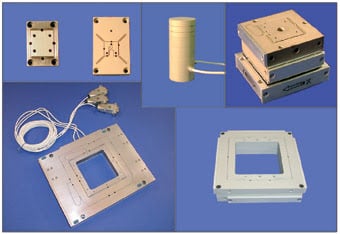
Figure 1. Miniature stages based on piezoresistive sensors can have vertical dimensions of 1/2-in. or less. Some also have lateral dimensions of less than an inch. One stage has a 2 × 2.5-in. footprint with a clear aperture and five degrees of freedom.
Mad City Labs has built and tested more than 25 nanopositioner designs that use piezoresistive sensors (Figure 1). Stages have one to five degrees of freedom as well as subnanometer precision. The main noise is the Johnson noise, which can be calculated as 0.03 nm for these examples. This low noise value is due to the sensors’ low resistance and high sensitivity (Figure 2).
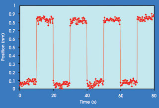
Figure 2. Shown is a typical step response for a nanopositioner based on a piezoresistive sensor. The noise comes primarily from the electronics, so the overall contribution of position noise from the sensor is negligible.
The devices also are highly linear (Figure 3). An example is a piezoresistive-based nanopositioner with a total range of motion equal to 100 μm and a measured nonlinearity of less than 0.05 percent. This corresponds to a half atom error when measuring a nanostructure 1000 atoms long. The hysteresis and creep of the stage also are almost negligible. No look-up table or high-order polynomial was used to correct for nonlinearities. Because linearity corrections are not needed for a piezoresistive sensor, the software or firmware overhead can be reduced, translating to higher speeds in nanopositioning.
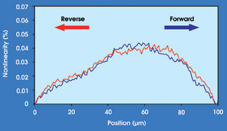
Figure 3. For one system, measured nonlinearity is less than 0.05 percent. No look-up table or high-order polynomial was used to correct for nonlinearities.
A number of high-speed piezoresistive-sensor-based nanopositioners also have been tested (Figure 4). One example is a large two-axis system built for microscopes that carries a petri dish, a slide or a glass flow cell. This nanopositioner can operate continuously at a velocity of 130 mm/s, which allows video rate data acquisition. Another system is a two-axis tip-tilt stage that has a full-amplitude 3-dB point of 1 kHz in closed loop, making it useful for video rate scanning, laser beam steering and high-speed laser beam cavity correction.
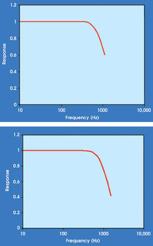
Figure 4. As indicated by its full-amplitude bandwidth, a large two-axis positioning system, which features a 75 × 75-μm range of motion and a resonant frequency above 2 kHz, can operate continuously with a full-amplitude 3-dB point of 400 Hz in closed-loop mode (top). The full-amplitude bandwidth for a two-axis tip-tilt stage made for laser beam steering shows a 3-dB point of 1 kHz (bottom).
As the requirements for nanopositioning increasingly dictate the need for smaller and higher-speed systems, piezoresistive sensors may very well become positioning standards. One driver may be future requirements that dictate microelectromechanical systems (MEMS) production of some nanopositioners. If that is the case, these sensors, which are ideally compatible with MEMS production, may see even more usage.
References
1. S.T. Smith and D.G. Chetwynd (1998). Foundations of Ultraprecision Mechanism Design, Vol. 2. Gordon and Breach Science Publishers, Amsterdam, the Netherlands.
2. Bjorn Andersen (2001). Piezoelectric components in the telecoms industry. Business Briefing: Global Photonics Applications and Technology. World Market Research Centre. Business Briefings Ltd., London.
Meet the author
William O’Brien is a member of the R&D group at Mad City Labs Inc. in Madison, Wis.