Coupled with a range of information-rich detectors, it provides the detection sensitivity required by diverse applications, from geochemical and environmental to agricultural, petrochemical, semiconductor and metallurgical analysis.
Michael Knowles, Varian Australia Pty. Ltd.
Over the past three decades, inductively coupled plasma, which forms during inductive heating of ionized gas, has become a valuable source for elemental spectroscopy. In induction-coupled plasma spectroscopy, plasma formation involves passing an inert gas, most often argon, through a quartz torch and imposing an electromagnetic field oscillating at high frequency on the gas flow at the end of the torch. Introduce a spark, and some of the inert gas will ionize. The resulting electrons oscillate under the influence of the radio-frequency field, creating more ions and electrons until a plasma forms that consists of ions of the inert gas and electrons oscillating rapidly under the influence of the electromagnetic field. Resistance to these oscillations translates into high temperature in the plasma.
The torch used for this process usually has three concentric quartz tubes, with the central tube used to inject liquid samples, usually in aerosol form, into the base of the plasma. The sample rapidly undergoes desolvation, atomization and ionization in the plasma. The elemental species introduced into the sample can then undergo electronic transitions that result in the emission of radiation characteristic of the element.
The first major type, inductively coupled plasma-optical-emission spectroscopy, evolved because different transitions result in different wavelengths of emission, which can be discriminated by optical systems. These will collect and separate the light and pass it on to a detector or detectors for measurement. In this way, the technique can detect elements down to low parts-per-billion levels in liquid samples (Figure 1).
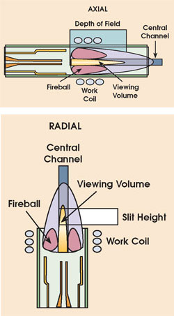
Figure 1. A modern ICP torch consists of three concentric quartz tubes. The central tube is used to inject liquid samples, usually in the form of an aerosol, into the base of the plasma. The sample rapidly undergoes desolvation, atomization and ionization in the plasma. The elemental species introduced into the sample can then undergo electronic transitions that result in the emission of radiation that is characteristic of the element. An axially viewed plasma is horizontal and viewed by the optics from the end. A radial plasma is vertical and is viewed from the side.
It also is possible to couple the plasma to a mass spectrometer as a detector. The challenge here is to couple the plasma at atmospheric pressure to a sensitive mass spectrometer that operates under high-vacuum conditions. This is done in stages.
The plasma is directed onto a metal sampling cone with an orifice of around 1-mm diameter in its tip. Behind the sampling cone, a vacuum pump lowers the pressure in this first stage to a few torr. The ions then pass through subsequent stages, with their flight paths conditioned by electrodes of different electrical potentials, until they arrive at the mass spectrometer and are separated according to their mass-to-charge ratio. The most common type of mass spectrometer is the quadrupole, a rapid, sequential scanning device that allows ions of one mass-to-charge ratio to pass to the detector at a time. The detector converts the incoming ions into pulses of electrons that can be counted by the instrument electronics.
The key advantage of this spectrometer type is its detection capability and ability to determine a wider variety of elements; in essence, it can measure virtually any element that can be ionized. Detection limits of parts-per-quadrillion levels are possible, although this demands cleanroom conditions for sample preparation and measurement.
Optical emission
Within the past decade, inductively coupled plasma-optical-emission spectroscopy has seen advances in detector technology, plasma viewing systems and torches. Key developments have come in the area of information-rich, solid-state detectors such as CCDs and charge-injection devices (CIDs). Such devices enable convenient, simultaneous detection of wavelengths from the plasma spectrum compared with photomultiplier tubes (PMTs).1 These detectors originally found use in either sequential scanning designs or in Rowland circle optics, which sometimes required the placement of up to 40 PMTs at each wavelength of interest on the circle. However, this multiplicity of detectors, which did not allow collection of all wavelengths of interest, was basically a sledgehammer approach to a problem requiring a simpler, more comprehensive solution.
The early 1990s saw the commercialization of both segmented-array CCDs and CID detectors. The first detector type has segments of active detector areas positioned across the surface to detect two to three primary wavelengths for each element, thereby continuing the inflexibility of previous PMT designs. It includes only 6336 pixels, resulting in just “5.7% coverage of the spectrum from 167 to 782 nm.”2 This approach, which is still used today, was presumably taken to circumvent problems of cost and data processing speed by restricting the number of wavelengths detected.
CIDs differ in principle in the way they handle collected charge on the detector surface. In essence, solid-state detectors convert incoming light into electrons on the chip surface for storage in potential wells or pixels. CIDs read each pixel without having to remove the charge it contains. In contrast, CCDs read the pixels by rapidly sweeping their contents off the detector and counting them. Unfortunately, reading the contents of each pixel in an array exceeding 2 million can be time-consuming in the CID format, which can cause problems with individual pixels over ranging, and potentially blooming into neighboring pixels. In addition, the circuitry required to process the contents of the pixels has traditionally reduced the transmission of light through the surface of the array, further aggravating noise problems.
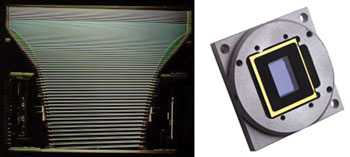
Figure 2. The CCD detector on the left (Vista-Pro) has rows of pixels positioned to exactly match the echelle spectrum. Light from the echelle spectrometer is separated into orders (vertical direction) and wavelengths (horizontal). This system promotes high processing speed. The megapixel-array CCD (MPX) has pixels positioned in an X-Y grid to give complete coverage.
To resolve such issues, Varian introduced a series of full-wavelength-range CCDs in 1998 for induction-coupled plasma instruments (Figure 2). The detector uses some 70,000 pixels arranged in continuous rows to detect the light from an echelle spectrometer, providing coverage from 165 to 785 nm. Such capability makes it possible to extend dynamic range by combining less sensitive wavelengths with the most-sensitive ones to provide accurate measurements from subparts-per-billion levels to percentage levels. A more recent system combines CCD technology with full-wavelength collection from an array of 1.1 million pixels.
Axial, radial or dual view
Conventional optical emission systems usually feature either a vertical torch, with the plasma viewed from the side (radial viewing), or a horizontal torch, with the plasma viewed end-on (axial). In the radial viewing technique, which is known for its robustness, the vertical plasma facilitates venting of the sample from the top of the torch, reducing torch blockage caused by sample deposition. However, axial viewing of the horizontal plasma can offer four to 10 times the sensitivity because of the longer path length of measurement, which can translate into superior detection limits. One concern, though, was that a horizontal plasma might be more prone to torch blockage from sample deposition.
An alternative dual-view approach uses a horizontal plasma with end-on viewing, coupled with a movable mirror for side-on viewing of the plasma. This design has two key problems. First, only one plasma view can be measured at a time, and the mirror for the side-on viewing must be moved into position and the sample analysis repeated. The horizontal plasma also restricts system performance to that of the sample-introduction system and torch. The horizontal plasma is prone to blockage and requires more frequent maintenance.
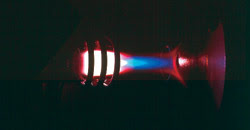
Figure 3. Horizontal, axially viewed plasma systems use a cooled cone interface to displace the cooler tail flame of the plasma away from the optical path. In this nickel cone of a cooled cone interface sampling the plasma, the red zone is the cooler zone of the plasma (while aspirating yttrium). The red zone is clearly displaced around the orifice of the cone.
One solution is to use horizontal, axially viewed plasma systems that employ a cooled cone interface to displace the cooler tail flame of the plasma away from the optical path, resulting in greater linear dynamic range and a significant reduction in atomization and recombination interferences (Figure 3).The axially viewed (horizontal) plasma has traditionally provided excellent long-term stability for samples containing up to 5 percent dissolved solids. With normal rinsing routines, these samples can be analyzed throughout the day using axially viewed, inductively cooled plasma. Most samples fall below this high dissolved-solids limit after preparation. For example, 1 g of soil, digested and diluted to 100 ml, represents 1 percent dissolved solids.
Recent advances in torches, spray-chambers and nebulizers are also allowing longer analysis periods for higher levels of dissolved solids. Options include double-pass spray chambers, V-groove nebulizers, wider-bore injector tubes and demountable axial torch designs. Selection of the appropriate sample-introduction system components can now translate into practical analysis of high levels of dissolved salts. To this end, Varian developed a torch that allows the direct analysis of 25 percent NaCl solutions for 24 hours of continuous aspiration (Figure 4).3
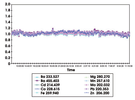
Figure 4. Results are from the continuous analysis of 25 percent NaCl solution over 24 hours using Varian’s Vista-MPX axially viewed, inductively coupled plasma (expected concentrations 1mg/l) with a high-solids torch. The solution was continuously aspirated without rinsing, and no internal standard correction was used. Relative standard deviation for the measurement period ranged from 3.3 to 5.2 percent.
Mass spectrometry
The past decade also has seen significant changes in quadrupole inductively coupled plasma-mass spectrometry. The primary disadvantage of this technique has been the occurrence of spectral overlap interferences caused by matrix and plasma species. For example, argon oxide that occurs naturally in the plasma causes an interference with the primary isotope of iron, 56Fe, because argon has an atomic mass of approximately 40 and oxygen has an atomic mass of 16.
Such interferences can occur from commonly found ions in the plasma, including argon, nitrogen, oxygen and hydrogen, and from the sample, all the analyte ions and matrix ions, such as carbon, nitrogen, hydrogen and silicon. To address these interferences, researchers in the past focused on instrumental techniques such as cool plasma and the development of new hardware such as collision cells.
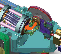
Figure 5. In the 90° reflecting ion-optics system of an inductively coupled plasma-mass spectrometer, ions enter through the interface region via the skimmer cone before being deflected (arrow) and focused by the circular ion mirror. Analyte ions are deflected, while photons and neutrals pass directly through the ring to a turbomolecular pump (shown swung away from operating position) directly connected to the interface region. Analyte ions are focused into the quadrupole mass analyzer. Curved fringe rods create a double off-axis system, which further reduces background noise.
In the cool plasma technique, for instance, the radio-frequency power of the plasma is substantially reduced and other plasma conditions changed to minimize ionization of the interfering species and, ultimately, their occurrence. The technique requires the creation of electrically neutral plasma to avoid discharge problems in the cones. One way is to use two inductively coupled plasma work coils that are interwoven and driven in opposite directions to create neutral plasma (Varian’s patented Turner interlaced coils).
Collision cell technology has another chamber prior to the quadrupole, allowing pressurized gas injection. Interferences are either reduced by collisional reactions that create noninterfering byproducts or through collisional reductions in kinetic energy that prevent the collisional byproducts from reaching the higher-potential quadrupole.
Unfortunately, these designs can slow down the productivity of the inductively coupled plasma-mass spectrometer, while requiring more specific conditions for each element. There also is added risk related to the use of dangerous reactive gases. Future developments in this field will probably focus on eliminating these disadvantages.
A recently introduced quadrupole inductively coupled plasma-mass spectrometry system produces tunable sensitivity equivalent to 1 × 10⁹ counts per second per part per million simultaneously with low interferences and background levels. This can be traced to a patented ion optics design. Instead of traveling linearly through the plasma-mass spectrometer interface, the ions reflect through 90°.4 Some 80 percent or more analyte ions passing through the skimmer cone are reflected by the ion mirror and directed to the quadrupole. This can translate to 20 times improvement in ion transmission when compared with the conventional, linear, inductively coupled plasma-mass-spectrometry systems.
Future directions
End users can only expect further advances in inductively coupled plasma spectroscopy, especially in efforts to generate more information from a sample. There is significant interest in determining not only the quantity of an element, but also the form in which it is present in the sample. For example, the toxicity of elements varies according to their oxidation state and molecular form. Hexavalent chromium is many times more toxic than trivalent chromium, and similar observations are true of oxidation states of arsenic and selenium. As another example, arsenite and its organic compounds are more toxic than those of arsenate. Organic forms of arsenic occur in the human body in the mono-, di- or trimethylated states as part of the body’s attempt to detoxify arsenic.5
From a spectroscopy perspective, determination of the form of these elements is paramount in a wide variety of environmental, pollution-prevention, geochemical and toxicological applications. Such analysis is largely done through hyphenated techniques — coupling a separation technique to the inductively coupled plasma-optical emission or mass spectrometry system, which essentially becomes a detector. It is likely that this trend toward hyphenated techniques to produce more information-rich results will continue.
Another area for development is sampling. Sample preparation for atomic spectroscopy can easily take 10 to 50 times longer than the sample analysis itself because solid samples are traditionally digested and diluted before being aspirated into the spectrometer. Laser ablation offers a viable alternative for many applications. A laser is directed at the surface of a solid sample to ablate the surface, and the ablated material is carried directly into the plasma for analysis.
This technique is particularly useful when coupled to inductively coupled plasma-mass spectrometers because the low amounts of ablated material demand high sensitivity and speed of analysis. Sensitivity can reach 1000 million counts per second with the latest inductively coupled plasma-mass spectrometer. Applications that can benefit include those in geochemistry, materials science, paleontology and archaeology, where the direct ablation of microscopic amounts of precious materials can be a significant advantage.
Areas such as these are already benefiting from recent application of inductively coupled plasma as a spectroscopy source. Both inductively coupled plasma-optical emission and mass spectrometry techniques (especially the latter) have found wider application through coupling with other methods of analysis or separation. The next decade promises to be just as productive.
References
1. J.M Harnly and R.E. Fields (1995). APPLIED?SPECTROSCOPY, pp. 334A-351A.
2. T.W. Barnard et al (1993). ANAL. CHEM. 65, 1231-1239.
3. Tran T. Nham (2001). Paper 0-18. Proc. European Winter Conference on Plasma Spectrochemistry.
4. Iouri Kalinitchenko (January 2003). A New ICP-MS System. Winter Conference on Plasma Spectrochemistry, Germany.
5. I. Kalinitchenko (Nov. 14, 2002). Ion Optical System for a Mass Spectrometer. Australian Patent No. 750860.
Contact: Michael Knowles, Varian Australia Pty. Ltd., Mulgrave, Victoria, Australia; e-mail: [email protected].