Atomic force microscopes perform accurate metrology without custom software.
Katerina Moloni, nPoint Inc.
Many atomic force microscopes (AFMs) and scanning probe instruments that provide usable images do not have closed-loop position control, which is essential for accurate, distortion-free visualization and metrology. The key to position control is accurate position sensing, and one of the most precise methods is noncontact capacitance sensing.
When used to characterize surfaces at the atomic scale, an atomic force microscope introduces distortion that usually is compensated for by application-specific computer algorithms. Active closed-loop control enables the microscopes to perform accurate metrology without customized software.
Closed-loop control uses an integral position sensor (usually a capacitive sensor) to achieve highly accurate nanopositioning. It enables the controller to reach and maintain a position set point by adjusting the control output based on feedback from the position sensors. Closed-loop control effectively removes image distortion caused by hysteresis and nonlinearity in the microscope’s piezo actuator. Hysteresis is the lag between the responding and changing parameters. In this case, position hysteresis describes the difference in actual position when the required position is approached from two directions.
Most atomic force microscopes without closed-loop control can be upgraded to metrology-capable instruments by replacing the existing scanner with a closed-loop X-Y scanner. This is accomplished through the AFM manufacturer or with a retrofit kit that provides the best possible nanopositioning technology. The system improves subnanometer accuracy, zoom capability and the ability to move quickly and precisely between image areas on the sample.
A 3-D map
In scanning probe instruments, the sample is scanned by a fine probe positioned within a few nanometers above the sample. In scanning tunneling and atomic force microscopes, a signal generated by the probe scanning position (X-Y) and distance from the surface (Z) is used to display an image of the topography in the same way that an electron beam paints a television or computer screen image. In other scanning probe instruments, the probe is designed to detect a specific physical or chemical property of the surface, such as magnetic field strength, heat capacity or refractive index. The result is a 3-D map of the property being investigated with atomic or molecular resolution.
It is possible to scan the surface of almost any solid. Biological objects can be imaged in a natural environment, such as in air or in fluids, whereas traditional high-magnification electron microscope examination requires an ambient vacuum. Even some dynamic processes can be imaged directly.
A scanning probe microscope introduces distortion that is compensated for by computer algorithms. Here again, active closed-loop control enables the scanning probe microscope to perform accurate metrology without customized software.
Open-loop control is acceptable when absolute position accuracy is not required or when an external sensor, such as a capacitive sensor or an interferometer, is used to measure position. Closed-loop control is necessary for applications where high-precision images will be used to quantitatively measure feature distances and dimensions. Combined with capacitive position sensing, it can achieve highly accurate nanopositioning. This approach allows the controller to reach and maintain the set point with high accuracy by adjusting the control output based on feedback from the position sensors. Closed-loop control effectively removes image distortion caused by hysteresis and nonlinearity in the piezo actuator (Figure 1).
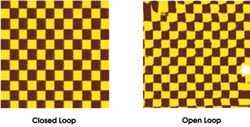
Figure 1. Closed-loop control removes the image distortion inherent in nonlinear piezo positioning. This distortion is most evident at the edges of the open-loop image.
A robust technique
Among the variety of techniques, one of the most robust is proportional integral derivative control. Tunable proportional integral derivative control algorithms can optimize response for many applications. Advanced control algorithms such as velocity feedback can be used to damp out mechanical resonances and to reduce settling time. This type of control gives the user the tools for in situ performance optimization.
Even though proportional integral derivative control is appropriate for a number of nanopositioning applications, it may not always provide the best response for a particular one. More advanced control techniques can be fine-tuned for a specific application to achieve better results in terms of response speed and accuracy. In an atomic force microscope trace/retrace (a line scan taken both forward and backward), the phase lag between trace and retrace is larger if the proportional integral derivative mode is used. This phase lag can affect the scanner’s positioning accuracy.
An ideal position sensor is a capacitance micrometer. This very high resolution noncontact device is one of the best choices for position sensing.
Although piezoresistive strain gauges can be used as position sensors, they have an accuracy limitation imposed by intrinsic 1/f noise that increases as frequency decreases. For most electronic components, 1/f becomes the dominant noise source at ~10 Hz. On the order of several parts per million, this noise will cause errors in the sensor reading. Strain gauge sensors have the advantage of small size; the reduced mass (on the order of milligrams) allows the stage to move faster. This advantage applies only to small stages that also must be rapidly positioned. Capacitance sensors do not have intrinsic 1/f noise.
Accurate positioning depends primarily on two factors: the sensor linearity and the mechanical design of the nanopositioner. The linearity is checked with an interferometer (Figure 2).
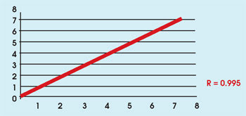
Figure 2. With closed-loop control, stage motion is linear in expansion and contraction of the actuator.
Reducing errors
Deviations from linearity are roughly parabolic. To achieve high positioning accuracy, a microprocessor compensates the sensor reading using high-order (fourth to sixth) polynomial corrections. The difference between the actual and measured distances forms a residual curve (Figure 3). A linearity error better than 0.1 percent of full scale is easily achieved. This means that, over a 100-μm range of motion, the position uncertainty is less than 100 nm. However, local variations in the residual gradients can be significant, though still within 0.1 percent of full scale. The use of a linear position sensor and higher-order polynomial fits can further reduce errors, to as low as 0.01 percent.
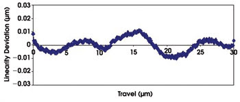
Figure 3. Linearity deviation is reduced to 0.03 percent after a sixth-order polynomial linearization correction.
One piezo or two?
Several factors can affect positioning accuracy, and they are associated more with the mechanical design of the stage than with the electronics. In some designs, two piezos are used to produce motion in one axis, increasing the stiffness of the stage and providing faster response. However, the two piezos expand differently with the same voltage, resulting in unwanted stage rotation that may not be detected by the motion sensors. Therefore, a single piezo is preferred.
Kinematic mounting can help reduce hysteresis and out-of-plane motion. Measurement repeatability under closed-loop control can be demonstrated by how well the images from scans in opposite directions match up (Figure 4).
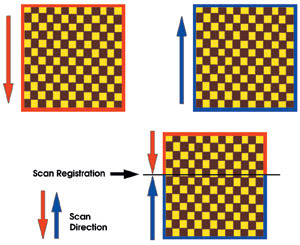
Figure 4. Repeatability is demonstrated by the registration of image scans made in opposing directions.
Installing a closed-loop scanner system upgrade provides subnanometer accuracy and exceptional scan linearity with none of the creep common to open-loop systems. Closed-loop functionality provides precise feature location, zoom capabilities and the ability to move quickly and precisely from one location within a sample to another. These are all characteristics that facilitate nanolithography, metrology and submolecular manipulation applications.
There are two ways to use an X-Y closed-loop upgrade system with an atomic force microscope. Working in conjunction with the microscope controller, the upgrade substitutes its X-Y scanner for that of the microscope’s head. When used in this manner, only the Z-scanner of the microscope’s head remains enabled. Alternatively, you can use the upgrade scanner as a precise sample-positioning device; in this case, all three axes of motion of the microscope’s scanner remain enabled. The kit is designed for installation on many atomic force microscopes without modification.
Meet the author
Katerina Moloni is vice president of marketing at nPoint Inc. in Madison, Wis.; e-mail: [email protected].