In automobile manufacturing, photonic testing offers unique advantages over mechanical methods.
Frank Chen and Daniel M. McKillip, Ford Motor Co.
For an automotive manufacturer to be successful in today’s fiercely competitive environment, continuous improvement is critical. Consumers are paying more attention to the ride and comfort that their automobiles provide, after vehicle function and reliability have significantly improved over the past decade.
Developing vehicles with the best and most cost-effective comfort and performance requires analytical, numerical and experimental methods and tools. Photonic techniques have unique advantages over traditional mechanical transducer-based measurement in many applications. One benefit is that light-based methods are virtually noncontact, compared with accelerometers using metal mass. Thus, using optical metrology to make vibration measurements eliminates mass-loading and local-stiffening effects. In addition, the technique is spatially dense and provides much more data than traditional methods; e.g., it provides data at every pixel in an image or at every scanning point.
Photonics has provided indispensable tools for high-frequency vibration measurement, flow visualization/quantification and high-gradient displacement measurement such as defect inspection. To understand the vibration pattern of a vehicle body or component (especially for transient vibration measurement) at high frequency, many accelerometers must be placed simultaneously on the object to be measured. However, the added mass and stiffness may alter the dynamic characteristics of the object; for example, when measuring the high-frequency vibration pattern of body panels or a rotating object, the advantages that photonics offers are compelling.
Interior noise
Vehicle interior noise can be air- or structure-borne. When noise comes from a direct leak from outside the vehicle body or from an air-induced panel vibration, such as wind or tire noise, it is considered airborne noise. If the body panel vibration is induced through a structural path, including road/tire wheel/suspension/body panel and power-train excitation, it is referred to as structure-borne noise.
Laser Doppler velocimetry is an advanced tool that can be used to measure body panel vibration at different frequencies under different loading conditions. Vehicle-development engineers must identify the high-vibration areas and deploy countermeasures to reduce vibration and, hence, noise.
One method for computing noise from body-panel vibration is a hybrid technique that inputs the measured panel velocity distribution into a finite- or boundary-element model to perform panel acoustic contribution analysis in terms of high-sensitivity panels and positive and negative contributions. Positively contributing panels act as sound sources; negatively contributing panels serve as sinks to cancel out sound at the receiving point. Once the positive, negative and high-sensitivity panels are identified, the treatment for reducing vibration can be implemented.
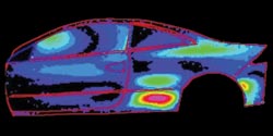
Figure 1. In the vibration pattern of a car body at 89 Hz, the hot spot appears as a red/pink area in the lower rear panel.
As an example, the vibration velocity of a car body has been measured at 89 Hz under a specific load case (Figure 1). There is a hot spot, or red/pink area, at the lower portion of the rear quarter panel. Treating the hot spot reduces the vibration of the panel and the interior noise. Laser Doppler velocimetry can quickly identify the hot spots and their cause. It also can be used to correlate a computer-aided engineering model that is a numerical simulation analysis tool.
Brake noise
Brake noise, or squeal, is caused by brake rotor and pad vibration when the rotor turns. The frequency range is usually between 1 and 16 kHz. Brake noise beyond range is usually beyond human hearing. Squeal can occur at either ambient or cold temperatures with or without high humidity. Cold squeal frequently happens the first few times that the brakes are applied during the first drive of the day, with humidity also being a factor. Hot squeals, on the other hand, occur after the brakes have been used several times and are warm.
The mechanisms that generate brake squeal are complex in nature. They involve multiple research disciplines, including nonlinear dynamics, contact mechanics and tribology/nanotribology, which is the study of the effects of friction on moving parts. The spatial and timescales of the concerned phenomena range from nanoscopic/microscopic to high frequency, further complicating the issue.
Computer-aided engineering methods based on finite-element analysis can diagnose and analyze the cause of brake squeal in tandem with real-world experiments. Critical to correlating test and analysis is the so-called operational deflection shape/pattern of the brake system during squeal. Because squeal occurs as the rotor turns, it is difficult or impossible to obtain the operational deflection shape using conventional transducer-based instruments, such as accelerometers.
With the traditional method, engineers need not only many accelerometers, but also a slip-ring device to pass the signal to the data-acquisition system while the rotor is turning. Scanning laser Doppler velocimetry has clear advantages over the conventional technique. By using a trigger-on-squeal scheme (scan while it’s squealing and quit scanning when it stops), the operational deflection shape of the brake can be obtained. This information can be used to compare the brake’s mode shape and to identify which mode contributes to the squeal. The mode shape of a brake system also can be measured quickly using this method (Figure 2).
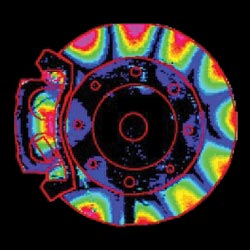
Figure 2. This mode shape of a brake system in the out-of-plane direction is sufficient to generate noise.
Airflow-induced noise
Aerodynamics or fluid mechanics can be employed to study airflow-induced vehicle vibration and noise and to study cooling/heat flow distribution inside a vehicle compartment. However, because of the complexity of the airflow around structures and components, aerodynamics cannot provide adequate or accurate results for all operational conditions. Tests such as flow visualization often are used to assist in determining the flow characteristics inside or outside the vehicle. The results can be used to optimize vehicle body shape or surface topography, to reduce wind noise, to optimize cooling/heating flow direction, distribution and efficiency as well as source position and flow direction.
A laser light sheet can serve as a very efficient light source to view small-particle motion in air driven by flow. In this way, the flow field can be visualized and characterized (Figure 3) and the design optimized accordingly.

Figure 3. A flow visualization test performed in a wind tunnel shows the airflow around a vehicle side mirror.
Deformation analysis
Strain or deformation measurement and analysis are performed continuously during structural strength assessment. The traditional technique incorporates strain gauges to measure an averaged strain at one location. But an optical technique can measure full-field strain or deformation of an object at every pixel on a recorded image, or hologram.
Called holographic interferometry, this method can register the three-dimensional image of an object; i.e., it records and reconstructs the wavefront. By comparing the recorded wavefronts before and after loading (double exposure), the deformation, or strain, of the object can be measured. Traditional holographic interferometry measurement and analysis counts the peaks and valleys of the fringe orders (the brightest and darkest location of fringes), losing the information in between. With the help of phase-shift techniques, the deformation in any pixel can be obtained, which is equivalent to having thousands or millions of strain gauges on the same part (Figure 4).
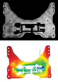
Figure 4. Holographic interferometry is effective for studying the deformation distribution of a vehicle component. Top is the raw data, and bottom is the color map of the contour of the deformation obtained by using a phase-shift technique.
Photonic tools have many applications in the automotive industry. Those that have been discussed here highlight some of the ways in which photonics has helped secure improvements in the quality, functionality, cost-effectiveness and reliability of automobiles. Other applications, such as dimensional control, manufacturing, design and lighting, are being equally affected by photonics-based metrology.
Acknowledgment
The authors would like to thank Pat Harwood and Jeff Bloomer for their innovative and fruitful work at Ford’s laser imaging laboratory.
Meet the authors
Frank Chen is a technical specialist at the Laser Imaging Lab of Ford Motor Co. in Dearborn, Mich.; e-mail: [email protected].
Daniel M. McKillip is a test development engineer at Ford.