Heating fiber optic sensors with in-fiber optical power enhances their versatility.
Kevin P. Chen, University of Pittsburgh
Fiber optic devices such as fiber gratings are key components for optical sensing and communications applications. They offer several important advantages over other optical and electronic techniques, including low manufacturing costs, immunity to electromagnetic fields, long lifetimes, high sensitivity and the ability to work in harsh environments. The small size and low transmission losses of optical fibers enable the deployment of sensor networks for multipoint and long-distance remote sensing. Fiber sensors embedded in structures can provide real-time information on structural deformations.
Despite the advantages of purely optical fiber components, their passivity has limited their performance and application. They cannot be reconfigured to adapt to new network topologies. Passive sensor elements do not support active adjustment of sensing parameters such as sensitivity, set point, triggering time, dynamic range and responsivity.
To enhance the functionality of fiber optic components, intensive research has been carried out in the past few years, directed toward the development of tunable fiber optic components such as fiber Bragg gratings. Tuning has been accomplished by several mechanisms, including electrical heating, the piezoelectric effect, mechanical stretching and bending, and acoustic modulation.
Despite this progress, a common drawback for active fiber components remains: An energy source, an energy delivery mechanism and on-fiber actuators are required to tune the device.
Extra cables
To date, the energy used to power an active device has been electricity. An electrical cable runs with the optical fiber to provide current for on-fiber heaters, to supply high voltage to drive piezoelectric actuators, to drive the step motors to bend gratings or to create an acoustic wave. This additional cabling, however, leads to many problems, including an increase in manufacturing costs as a result of the additional on-fiber electrical contacts and packaging, the sacrifice of electromagnetic immunity, increases in size, and difficulties associated with embedding materials and structures. The electric wire and rubber cable — rather than the durable silica fibers — determine the lifetime of the device. Similarly, the device is no longer suitable for use in hostile environments such as high humidity, a corrosive atmosphere, high g and strong electromagnetic interference.
The dilemma is that the performance of an electrically driven component is improved at the expense of the many intrinsic advantages of a purely optical component. The solution is to power the component with light.
If we take a close look at an optical fiber, we see that it is simply a cable for delivering optical energy. And if an optical-sensing signal can be delivered through a fiber, why can’t we use the same fiber to deliver power optically?
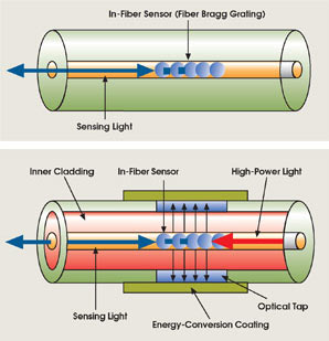
Figure 1. (a) Traditional fiber Bragg gratings are interrogated by sensing light, but they cannot be adjusted to accommodate changing conditions. (b) The proposed active grating is heated by high-power light, enabling adjustment of its properties, including resonant wavelength, chirp and polarization-mode-dispersion set point.
This concept is illustrated in Figure 1. In contrast to a passive sensor, the optical power in the active device is delivered together with a sensing signal through a fiber that contains components such as fiber Bragg gratings. Double-clad fibers are ideal for delivering both the optical power and the sensing signal. An optical tap is fabricated in desired sections of the fiber to release high-power laser light. An optical conversion membrane coated on the outer surface of the fiber serves as a transducer, converting laser energy to the thermal energy that changes the optical characteristics of the component.
This power delivery scheme eliminates the need for electrical power, cables, electrode/fiber contacts and associated packaging.
We have explored this novel idea and demonstrated the tuning of a fiber Bragg grating with optical power. We wrote the grating in Corning SMF-28 standard single-mode fiber and monitored the reflection spectrum from a broadband source using an Ando 6317C optical analyzer (Figure 2). We fusion-spliced the fiber to a 100-μm-core multimode fiber with a 140-μm diameter and a numerical aperture of 0.22.
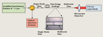
Figure 2. The reflectivity of a fiber Bragg grating sensor in a single-mode fiber can be adjusted using the output of the laser diode. The output of a high-power laser diode was coupled by microscope objectives into a multimode fiber, which was fusion-spliced to the single-mode fiber. The fusion splice is shown in the inset. In more sophisticated arrangements, the single grating can be replaced with an array of elements.
We coupled 10 W of 910-nm laser radiation from a high-power diode laser array into the end of the multimode fiber using a pair of 20× microscope objectives. Using the cut-back method, we estimated that 90 percent of the IR radiation was lost within the 10-cm section of the single-mode fiber closest to the fusion-spliced junction. The leaking radiation was subsequently absorbed by the metallic coating, which created heat and raised the temperature of the fiber Bragg grating.
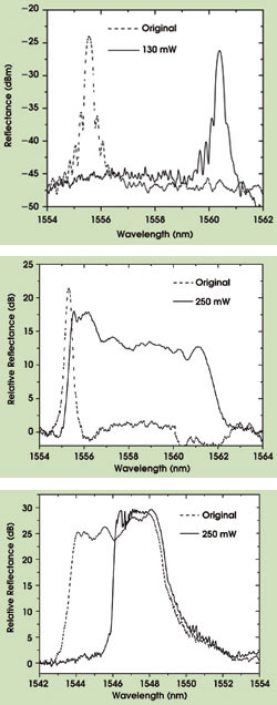
Figure 3. (top) The 130 mW of optical power shifted the resonance of the 4-mm-long fiber Bragg grating in Figure 2 by 4 nm. (b) In a 4-cm grating, the thermal gradient created by the 910-nm power traveling from the right in Figure 2 causes a frequency chirp in the reflected radiation. The chirp shows up here as a broadening of the reflected light, from 0.4 to 6 nm. (bottom) Heated by the same input laser power, a 4-cm linear chirped grating displays spectrum compression, the opposite effect from that in (middle).
Figure 3a shows the spectrum evolution of a 4-mm uniform grating heated by 130 mW of 910-nm laser radiation. Because the thermal mass of the grating is only 200 μg, the absorption of this laser radiation raised the temperature dramatically and shifted the resonance wavelength by as much as 4.9 nm.
The laser energy leaking from the fiber cladding falls off exponentially with distance (assuming a constant loss coefficient); thus, a temperature gradient is created in longer fiber Bragg gratings. The temperature gradient modifies the spectral response of the grating and introduces a frequency chirp.
Spectrum stretch
Figure 3b shows the spectrum stretch of a 4-cm-long uniform grating with a 0.4-nm spectrum width. The 250 mW of diode laser radiation raised the grating temperature from the input side and increased the background index, which stretched the width of the spectrum to 6 nm. The reflection spectrum is not flat, suggesting a nonlinear chirp due to a possible exponential temperature gradient in the fiber. By adjusting the coating composition and profiles, it should be possible to control the temperature gradient in the uniform grating to produce gratings with an arbitrary chirping profile.
The tuning flexibility of optically powered fiber Bragg gratings can be further demonstrated by chirped grating spectrum compression (Figure 3c). Diode laser radiation of 250 mW was launched into a 4-cm linear chirped grating (2 nm/cm chirp) from the short-wavelength side. The temperature gradient created by the laser in the grating “dechirped” the grating and compressed the width of the spectrum from 8 to 4 nm.
An advantage of optically powered fiber Bragg gratings is their ability to produce a very small local index change by generating a local light absorber to tailor the reflection spectrum of a chirped grating. We placed a 2-mm-long silver film on the middle of a 4-cm-long, linearly chirped grating (1 nm/cm chirp) whose peak reflectivity was 99 percent. The laser-induced rise in temperature at the silver film changed the local refractive index and shifted the resonance wavelength of the chirped fiber Bragg gratings at the heated zone. As a result of the reduced grating strength in the heated region, a notch appeared in the reflection spectrum (Figure 4a), and we were able to vary the depth of the notch from 0 to 9 dB (Figure 4b).
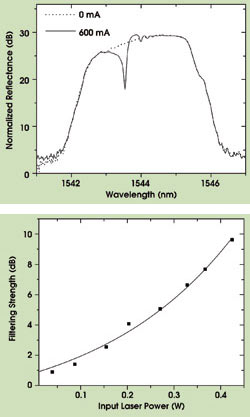
Figure 4. (top) Heating a small subsection of a chirped fiber Bragg grating diminishes the reflectivity of that section and creates a notch in the reflected spectrum. (bottom) The strength of the notch filter depends almost linearly on the laser power.
Fiber Bragg gratings are commonly employed as passive temperature and pressure sensors. The ability to adjust these devices optically introduces a new dimension for the design of agile and multifunctional fiber sensors without compromising their intrinsic advantages. We have demonstrated two novel devices using this capability: a flow sensor and a level sensor, both of which are based on the principles of hot-wire anemometry.
At present, most state-of-the-art miniaturized flow sensors are fabricated on silicon substrates using microelectromechanical systems (MEMS) technology. MEMS flow sensors based on both heat transfer and differential pressure measurements have been extensively investigated. Although they offer important benefits such as compact size, high sensitivity, fast response time and compatibility with CMOS technologies, they also have a number of drawbacks.
First, although MEMS flow sensors using silicon micromachining techniques are miniaturized, the packaging can be bulky and involves at least two electrical connections: one for the power supply and one for the sensing signal. This limits the usefulness of the sensors for a number of important applications in harsh environments. These include fuel injection rate measurement for cryogenic engines, flow measurement in conducting and corrosive gases and liquids, flow measurement in strong electromagnetic fields such as in a nuclear magnetic resonance chamber, and flow measurement in confined tubing and respiration devices for medical purposes.
To demonstrate flow sensing, we silver-plated a short and strong (>99% reflectance) 5-mm grating with a center wavelength of 1554.9 nm and fusion-spliced it into the configuration shown in Figure 2. Without nitrogen flow, 384 mW of laser power from the 910-nm diode (~50 mW of which was absorbed by the metal coating) heats the fiber Bragg grating and shifts its resonance wavelength by 3.3 nm to 1558.2 nm (Figure 5).
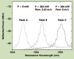
Figure 5. The location of the fiber Bragg grating’s reflectance peak in the absence of optical heating (Peak A) is temperature-dependent and can be used to measure temperature. When the grating is optically heated in still nitrogen, its reflectance peak shifts to a longer wavelength (Peak C). When nitrogen flows across the grating, it cools it, and the reflectance peak moves back to a shorter wavelength (Peak B). The amount of movement is a function of the nitrogen flow rate.
We deliberately chose 5-mm-long gratings in this experiment to avoid spectral distortion caused by the nonuniform light absorption profile. If the grating is heated to a higher temperature, a given flow rate causes a greater temperature change than if it is heated to a lower temperature. Thus, the measurement sensitivity can be adjusted by changing the laser input power.
Temperature sensor
With the 910-nm laser turned off, the fiber Bragg grating serves as a temperature sensor for ambient gas, just as a normal passive one would, and the resonance wavelength is noticeably affected by the presence of gas flow because it’s at thermal equilibrium with the gas. With the 910-nm laser turned on, the introduction of the N2 flow increases the heat-removal rate from the grating and reduces the temperature of the sensor, which shifts the resonance wavelength (Figure 5). The shift can be calibrated to yield a measurement of the flow velocity for both gases and liquids.
This grating flow sensor has been evaluated at different grating lengths and input laser powers. The preliminary results indicate a 0.35-m/s sensitivity for nitrogen flow at atmospheric pressure. This is equivalent to a flow rate of 0.38 liters per minute in standard 0.25-in. tubing (inner diameter of 4.8 mm), which is comparable to or better than most MEMS-based flow sensors. The sensitivity can be further improved by increasing the thermal contact between the grating and the surrounding fluid.
Monitoring the level of a liquid is important in many industrial and space exploration applications. A number of sensing principles employing fiber optics can do so in a tank or other container. The optimal choice in sensing technology depends on the liquid, the application environment, reliability and cost.
The solution to level-sensing problems can be complex for harsh environments such as space. For example, the level of liquid hydrogen in cryogenic fuel tanks for space missions is detected using an array of silicon diode point sensors, which are heated by current pulses. When a diode is submerged in liquid hydrogen, its temperature rise is limited by the boiling point of hydrogen. The temperature difference between the diodes above and below the fuel level indicates the liquid level. Because liquid fuel does not settle to the bottom of the tank in a microgravity environment, a large number of point sensors are required to precisely gauge the amount and distribution of fuel.
Each sensor requires two metal leads to measure the voltage and supply current to the sensor. This results in a large number of electric feed-through lines for one cryogenic fuel tank, increasing heat leakage and the potential of mechanical and electrical failure. In space, the large number of electronic sensors and metal leads is susceptible to electromagnetic interference because any AC current imposed upon them is rectified and appears as an erroneous temperature offset.
Using optically heated fiber Bragg gratings, we have demonstrated a dual-function (level/temperature), self-powered fiber sensor for cryogenic fuel management. Optical energy carried by a multimode fiber heats a grating sensor, and the thermal response of the sensor — sometimes in liquid and sometimes in air — is transmitted back through a single-mode fiber (Figure 6a).
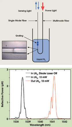
Figure 6. (top) The sensor introduced in Figure 2 can measure the level of a cryogenic liquid. (bottom) The broken line is the grating reflectivity when the power is off, whether the grating is above or below the liquid N2 surface. The solid black line is the response when the grating is below the surface, and the solid red line is the response when it is above the surface.
Figure 6b shows the response of the grating above and below the surface of liquid nitrogen. When the grating is above the surface, it can be heated above the boiling point of liquid N2, and its reflectivity changes. But when it is immersed, it is locked to the boiling temperature of the liquid, and the heat dissipated at the grating is absorbed as heat of vaporization in the liquid N2.
Future research
An inherent drawback in the systems we have demonstrated so far is the necessity of employing two fibers — a single-mode one to carry the probe signal, and a multimode one to carry the power — connected to the fiber Bragg grating. Not only is this arrangement more mechanically awkward than using a single fiber, but it also wastes considerable optical power because the power that leaks from the splice between the two fibers is distributed across the entire single-mode fiber, and only a fraction is converted to the heat that adjusts the grating’s characteristics.
We want to focus on combining these two functions in one double-clad fiber. The probe signal will be launched into the core, and the power will be launched into the inner cladding. This will simplify the mechanical design by eliminating one of the two fibers connected to the fiber Bragg grating, and it will reduce the energy loss because power in the inner cladding can be more efficiently coupled to the conversion device that heats the grating.
Meet the author
Kevin P. Chen is the Paul E. Lego assistant professor of electrical engineering at the University of Pittsburgh; e-mail: [email protected].