Novel ways to use light (and sometimes sound) can help locate and characterize invisible defects.
Hank Hogan, Contributing Editor
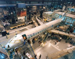
At the Federal Aviation Administration’s (FAA) William J. Hughes Technical Center at the Atlantic City International Airport in New Jersey, Robert A. Pappas and others like him sweat the small stuff. Among their other activities, the engineers conduct research on aging aircraft; specifically, on how materials and structures — such as aircraft frames — change with age. They also seek better ways to inspect for and mitigate those changes.
These are important endeavors, especially to travelers cruising along at 30,000 feet with nothing between them and the sky but a few millimeters of metal.
 “We research issues specific to continued airworthiness of aircraft that are out there in operation today,” explained Pappas.
He added that nondestructive inspection, which can entail photonics technologies, plays an important role in these efforts. Nondestructive techniques also are used by commercial airlines during their periodic assessments of the airworthiness of their aircraft. A look at some inspection technologies reveals how photonics helps keep planes flying.
Crack detection heats up
One of the newest photonics-based inspection technologies involves both sight and sound. David Galella, a project engineer at the FAA technical center, noted that a technique known as sonic IR can spot small cracks before they become bigger and more dangerous. “Sonic IR is pretty exciting because what we think we’re seeing is the tip of the crack,” he said.
Such cracks are usually spotted using eddy current or ultrasonic technologies. In the eddy current approach, a probe is placed on each rivet, through which a current is driven into the aircraft’s metal skin. That sets up eddy currents, which are detected and mapped to uncover cracks. This technique, as well as other inspection methods, works but is labor-intensive. It covers only a small area, so inspectors are forced to test at one rivet, move to the next and repeat the procedure. Consequently, they expend a lot of time and money in maintaining airworthiness.
In contrast, sonic IR offers the possibility of covering larger areas without sacrificing sensitivity. Lawrence D. “Skip” Favro is director of the Institute for Manufacturing Research at Detroit-based Wayne State University and a member of a research group there that has been investigating this technology for the FAA and other organizations. He explained the technique by noting that, when sound propagates through a material, the material moves. If a crack is present, the two sides don’t move in unison. Instead, one side rubs or claps against the other.
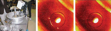
An early version of the sonic IR system developed by Wayne State University researchers is used to inspect an aircraft wheel (left). The ultrasonic source is shown in the bottom left and the IR camera, above the wheel. With no ultrasound applied, an IR image of one of the wheel’s bolt holes shows no cracks (center). With ultrasound activated, the IR image clearly shows the presence of a crack around the hole from the 6 to the 9 o’clock positions (right). Courtesy of the Federal Aviation Administration.
“You get heat, just like the Boy Scout trick of rubbing two sticks together,” Favro said.
This heat starts at the crack and spreads outward. To pinpoint the crack, the Wayne State researchers use a pulsed ultrasonic source — an ultrasonic welder that operates at 20 or 40 kHz and at ~1 kW. They hold the welder against a metal aircraft frame or other part and fire it for about 0.1 to 0.5 s.
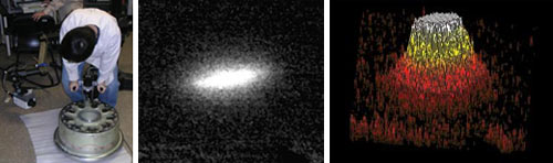
With the sonic IR inspection system, ultrasound can be applied anywhere near a potential crack or other defect — in this case, anywhere along the circumference of the wheel (left). IR imaging reveals a crack in the wheel (center) and provides data for a 3-D plot that represents that crack (right). Courtesy of Lawrence D. Favro.
Tests have indicated that it doesn’t matter where the ultrasonic source is in relation to the crack as long as it is reasonably close. But the frequency seems to have an effect, with different frequencies highlighting different lengths and types of cracks better. For that reason, the Wayne State group has been looking at creating broadband acoustic sources. “If you can put in a broad spectrum, you have a lot better chance of finding the cracks,” Favro said.
For detection, the group uses an IR video camera running at ~100 fps. Fabricated with an array of 640 × 512 InSb pixels, the camera picks up the heat produced by the crack in response to the sound. According to Favro, the heating is instantaneous with the beginning of the pulse. If the crack is on the surface of the part, the heat is immediately detected. If the crack is a subsurface one, the heat must first propagate through the material before it can be spotted. As a result, the heat signature spreads out and there isn’t a sharp line, but the time it takes the heat to appear once the ultrasonic pulse begins provides data to calculate the crack’s depth.
The smallest crack detected by the sonic IR technique — and independently verified by other methods — measured 20 μm. The area of the field of view of a sonic IR device is a function of the optics and the proximity of the camera to the tested part. To ensure that what’s being captured is a crack and not simply a bad pixel, the camera must be close enough so that the defect shows up across multiple pixels.
On the other hand, some defects — such as delamination — measure inches across. The researchers have spotted such problems using sonic IR on test parts that have a field of view several feet long and a couple of feet wide.
Fast cameras
According to Favro, the technique doesn’t require special cameras. However, the cameras must be fast enough to record the rapid thermal bloom that arises from the high diffusivity of heat in metal, and this means that the integration time for the detector array needs to be on the order of a few milliseconds when metals are involved. The thermal characteristics of composites, on the other hand, mean that much slower cameras will suffice. No matter which type of camera is used, the standard technique is to run it for a period of time to acquire a background reading. Then the researchers fire an ultrasonic pulse and start the crack-and-defect detection process.
One key, Favro noted, is that care must be taken to ensure that any image picked up isn’t the result of someone walking by or of something else unrelated to the ultrasonic pulse. “Synchronization between the camera and the ultrasonic pulses is important,” he said.
He pointed out that the technique has been patented by Wayne State and that there are commercial products from various companies based on the technology. There are no commercial applications to aircraft inspection yet, but that could change as a result of ongoing research and development.
Keeping it clean
Commercial manufacturers also use photonic inspection techniques as part of the aircraft production process. For those such as Boeing Co. of Chicago, cleanliness not only is next to godliness, but also improves a product. After an aircraft is primed and painted, contaminants trapped under the paint can cause cosmetic problems, such as when the paint fails to adhere. Contaminants also can compromise the corrosion resistance of fasteners, which can potentially have a much more serious effect.
The problem is that some contaminants can be virtually invisible to the unaided eye, which has been the standard tool for inspectors. Boeing’s materials and process technology group has developed a working prototype of an optical detector that spots such contaminants spectroscopically. Edward G. Sergoyan, an engineer in vision, sensors, and optics research and development at Boeing Commercial Airplanes in Seattle, was part of the development group. He said that the detector has successfully located various amounts of soap, lubricants, corrosion inhibitor, greases, solvents and oils in isolated areas on an airplane’s surface. This was done using custom lenses, portable white-light and ultraviolet sources, and a low-light CCD camera.
Although the technique works in spotting a dozen contaminants for further chemical analysis, there are limits to what can be inspected. “The contaminant can only be successfully detected if it can be photonically excited and made to fluoresce,” Sergoyan said.
He noted that Boeing isn’t in the instrument-building business. When the development work is done, and if the prototype is approved for manufacturing, the company will contract with an outside manufacturer to produce the instrument. At that point, it’ll be supplied to Boeing and anyone else who is interested.
The shape of things to come
Bombardier Aerospace, a part of Montreal-based Bombardier Inc., is the No. 3 company worldwide when it comes to civil aircraft manufacturing. It makes a variety of business and regional jets and other aircraft, the external contours of which are complex shapes — three-dimensional surfaces with curvatures in every direction. For manufacturers, the problem is ensuring that the shape produced is the one that was designed. To do that, Bombardier turns to laser ranging devices.
“The equipment can map out a cloud of points on those actual surfaces and reproduce those points in a computer environment,” said Marc St.-Hilaire, director of core engineering at Bombardier.
These inspections are not part of the regular manufacturing process. Rather, the technology is used to set up the jigs for machining and to confirm that a piece has been produced correctly. The tolerances of the machined parts range from ±0.005 to ±0.060 in., with only the most critical zones being constrained to the tighter tolerance.
The laser rangefinders, which replaced a camera-based system, have automated the inspection process of the manufacturing setup. However, this hasn’t necessarily translated into as much setup time savings as one might expect because, with the greater capability, there’s a tendency to collect more information.