Through succeeding generations, image intensifying devices have brought vision to the dark of night.
Harry P. Montoro, ITT Night Vision
Image intensification, the basis of night vision, is a complex conversion of energy particles that occurs within a vacuum tube. An image-intensifier system works by collecting photons through an objective lens, converting them to electrons via a photocathode, increasing the electrical energy with a microchannel plate (MCP), converting the electrical energy back to light using a phosphor screen and presenting the image for viewing through an eyepiece lens.
A sophisticated miniaturized power supply is used to provide the voltages between the elements of the vacuum tube that allow for the energy conversion and amplification. All of the elements within the vacuum tube are closely spaced to avoid electron scatter.
The main electron amplification occurs within the MCP, a thin disc that contains millions of closely spaced channels. As the electrons pass through the channels and strike the channel walls, thousands of additional electrons are released. When these strike the phosphor screen, the increased energy is reconverted into light thousands of times brighter than that which entered. The phosphor screen emits this light in the same pattern as the light collected by the objective lens, so the brightened, intensified image seen in the eyepiece corresponds to the scene being viewed (or not viewed) in the dark.
The generation gap
In the night-vision world, the word generation (Gen) refers to major advancements in technology. The higher the generation, the more sophisticated the night-vision technology. The generation gap is the change in technology that drives the change in nomenclature.
During World War II and the Korean War, the art of stealth warfare had taken hold, and formal sniper training had become a part of military maneuvers. It was during these years that the image-intensification progression began.
Early snipers used image converters (sniperscopes) that required an infrared light source to illuminate their target. Known as Gen 0, these image converters evolved from RCA’s image converter tube developed in the mid-1930s for use in televisions. The Gen 0 image converter used an S-1 photocathode, an IR-sensor with a high-voltage electron acceleration electrostatic field and a phosphor screen. The S-1 cathode (AgOCs) did not have as much quantum efficiency as the cathodes used today, but it was able to provide images with the help of the IR illuminator (Figure 1).
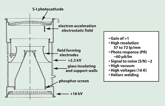
Figure 1. Gen 0 tube design and makeup.
The process by which the image was intensified was quite simple in this generation. The reflected IR illuminator light entered the tube and the photocathode converted the light to electrons. Electronic elements focused these electrons through a coneshaped component (anode) and accelerated them using very high voltage so they hit the phosphor screen with greater energy, recreating a visible image. Accelerating the electrons in this manner did not produce much gain and caused distortion in the image. Also, tube life was not very good by today’s standards.
Generation 1
The starlight scope, developed during the early 1960s and used during the Vietnam War, was made using Gen 1 image-intensifier tubes. In this scope, three image-intensifier tubes were connected in series, making the unit larger and heavier than today’s night-vision goggles. This early generation produced a clear center image with a distorted periphery. The use of multiple tubes connected in series allowed for much greater overall light gain as the output of the first tube was amplified by the second and the second by the third. Due to the simple power supply design, the image was subject to instances of blooming — momentary image washout due to an overload in the intensifier tube caused by bright light sources (Figure 2).
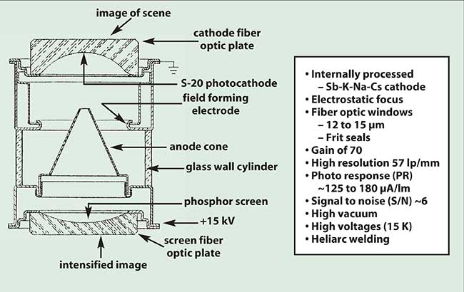
Figure 2. Gen 1 tube design and makeup.
The primary difference between Gen 1 and Gen 0 was the more sophisticated chemical process employed to create the photocathode. The S-20 cathode, a multi-alkali antimonide process, enhanced the sensitivity as well as the spectral response. However, Gen 1 did have some of the same drawbacks of image distortion and decreased tube life as seen with Gen 0. Tubes built with Gen 0 and Gen 1 technologies are commonly found in many of today’s imported night-vision viewers.
Generation 2
Developed in the late 1960s, Gen 2 technology brought a major breakthrough in night vision with the development of the microchannel plate. Additionally, the photocathode process used for Gen 1 was further refined to the S-25 cathode and produced much higher photo response.
Nevertheless, it was the introduction of the MCP that made Gen 2 unique. The MCP begins with two dissimilar pieces of glass. A large tube of solid glass (core) is placed within a tubular sleeve of glass (clad). The two glasses are then heated together and stretched to form a very small diameter glass fiber. The fibers are ultimately compressed together to form a bundle of glass fibers called a boule. The boule is then sliced at an angle to obtain thin discs. Further chemical processing removes only the core glass, thus creating the channels within the MCP. During the tube operation, the electrons travel into the channels and, as they strike the channel walls, they produce secondary electron emissions which create several hundred electrons (Figure 3).
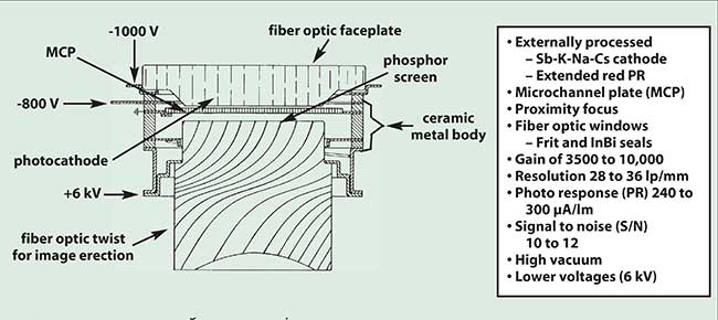
Figure 3. Gen 2 tube design and makeup.
The close spacing of the channels within the MCP, along with the close spacing of the MCP to both the photocathode and the phosphor screen, allow an image to be created without the distortion characteristic of the Gen 0 and Gen 1 tubes. However, the channels within early MCPs were quite large compared with today’s MCPs. As such, the resolution within early Gen 2 tubes was not as good as that of Gen 0, Gen 1 or today’s Gen 2 and Gen 3 tubes.
The other advancement with Gen 2 was the reduction in overall size and weight of both the tube module and the power supply. This reduction allowed Gen 2 tubes to be the first image intensifiers used within user-mounted devices such as head- and helmet-mounted goggles.
Generation 3
Developed in the mid-1970s and placed into production during the 1980s, Gen 3 was mainly an advance in photocathode technology. The overall appearance between Gen 2 and Gen 3 tubes is quite similar. Gen 3 tubes use gallium arsenide (GaAs) for the photocathode. This increases the tube’s sensitivity dramatically and particularly in the near-IR. The increased sensitivity improved system performance under low-light conditions, or, to put it another way, enabled the tube to detect light at far greater distances.
However, the highly reactive GaAs photocathode could be easily degraded by the inherent chemical interactions that take place within a tube under normal operation. Most of the chemical reactions take place within the MCP due to the electron interactions with the walls of the MCP channels. Thus, to overcome the degrading effects of the photocathode, a thin metal-oxide coating was added to the input side of the MCP. This coating, more commonly known as an ion barrier film, not only prevented premature degradation of the photocathode but also enhanced the tube life by many times that of the Gen 2 tubes.
This improvement continues to be a significant performance difference between Gen 2 and Gen 3 tubes. The film can, however, impede the photoelectrons from entering the MCP, so intrinsically it increases the electronic noise component of the tube. A major measure of overall performance for an image-intensifier tube is known as the signal-to-noise ratio, or SNR. The signal component comes directly from the photocathode sensitivity. The noise component comes from the combined effect of various operational aspects of the tube, both physical and electrical. The substantially higher photoresponse of the Gen 3 photocathode more than offsets the increased noise component (due to the ion barrier film), providing Gen 3 with a significant improvement over Gen 2.
Both Gen 2 and Gen 3 tube manufacturers have made continuous improvements through the years to increase the signal-to-noise ratio within each respective technology. Additionally, continuous improvements have been made within MCP manufacturing so as to improve the overall resolution also (Figure 4).
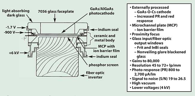
Figure 4. Gen 3 tube design and makeup.
There has been considerable effort expended in developing a Gen 3 tube without the ion barrier film. The effort proved successful, but the manufacturing costs were excessive compared to the performance improvements. For a brief period of time, the Gen 3 tube without the ion barrier film was termed Gen 4. This terminology, however, was rescinded shortly after it was announced, though some resellers of night-vision tubes still use the nomenclature.
Continuous developments
Gen 2 and Gen 3 technology have transitioned through a long time of continuous development with tremendous improvements within each of these technologies.
One area that has contributed to the improvements is the advancement of the miniature high-voltage power supply. Early developments with the power supply included protection circuits to automatically control the output brightness of the tube under changing input light conditions. These effects, known as automatic brightness control (ABC) and bright source protection (BSP), were directed at protecting both the image tube from highlight exposure and the user’s eyes from excessive brightness. The ABC automatically reduces voltage to the microchannel plate to keep the image intensifier output brightness within optimal limits and to protect the tube. This effect can be seen during rapid changes from low-light to high-light conditions when the image gets brighter and then quickly returns to a consistent level. The BSP reduces voltage to the photocathode rather than the microchannel plate. The BSP protects the image tube from damage and enhances its lifetime.
Under high-light conditions, the scene resolution can be degraded. Advancements in miniaturized power supplies include the addition of autogating circuits. These circuits control the way the photocathode is operated under changing input light conditions. Autogating allows the image tube to be used under higher input lighting with much less degradation of the image quality.
Autogating turns off the photocathode voltage for brief periods of time, but the effect is not visible to the human eye. The cathode voltage is constantly oscillating, but the image appears as if it were continuous. The autogating circuit reduces the time the voltage is on during each oscillation but keeps the peak voltage level up. By controlling the application of voltage in this manner, the resolution quality remains high. In effect, the autogating feature tricks the device into thinking it is always in a low-light environment, which is the optimal environment for maximum efficiency and clarity for the image-intensifier tube. While the most obvious effect of autogating for the user may be improved resolution in high-light conditions, its original purpose was to help extend the lifetime of the tube, a benefit which is most realized with thin-film or filmless tubes.
As opposed to the gradual lifetime decay seen in tubes without an ion barrier film, the Gen 3 tube with gating and the use of a thin film improves tube life and performance far more than any other image-intensifier technology. Typical reliability is well in excess of 15,000 hours without noticeable degradation. This change in durability is a significant accomplishment when considering the much shorter lifetimes of Gen 0, Gen 1 and Gen 2 tubes.
What’s next
Image-intensifier technology has most widely been associated with use in night-vision goggles (NVGs). Another major technology, unrelated to image intensification, yet referred to as night vision, is that of thermal or IR imaging. Image intensification and thermal imaging each have comparative strengths and weaknesses. Thermal imagers are quite good at detecting heat sources in total darkness, such as body heat of personnel or engine heat; however, they do not have as high a resolution as do image intensifiers (at equivalent fields of view). Such is because thermal imagers provide an electronic output and the pixel size of the focal plane array (FPA) is much greater than the “effective” pixel size of the direct view optical output of the image intensifier tube. Additionally, thermal imagers had for many years been impractical for user-mounted applications, like NVGs, because of their greater size, weight and power (SWaP) consumption. Advances in recent years with uncooled thermal imagers such as vanadium oxide and amorphous silicon, have greatly improved these features making them more suitable for head-mounted applications.
It is easy to imagine myriad situations in which users would greatly benefit from the attributes of both thermal and image-intensification devices at the same time. Thus the logical progression would be to build one device that brings the benefits of both technologies together.
Sensor fusion
Sensor fusion combines the respective strengths of thermal and image-intensification technologies into one device. By combining the strengths of both technologies, users can view a much greater portion of the light spectrum – visible to near-IR to long-wave infrared. The ability to see information from both the visible and thermal spectrums through one device represents a significant advantage to military, security and law enforcement personnel (Figure 5).
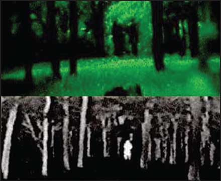
Figure 5. Woodline seen through Gen 3 night-vision device (top) and seen with IR technology (bottom).
The desire to fuse these two technologies – and keep the overall SWaP consumption low so the device can be worn by a person – is leading to the development of new night-vision technologies and devices. The primary device is the enhanced night-vision goggle (ENVG) that combines a thermal imager with an image intensifier. In the ENVG, the image intensifier works like a standard NVG. However, the image from the thermal sensor is presented on a video display and then optically overlaid with the image-intensifier output. The future desire is to combine the video output of a thermal imager directly with the video output of an electronic output image intensifier. These new devices could then present a complete digitally fused image to a HMD in a device known as the digitally enhanced night-vision goggle (ENVG-D).
Leading the technology development in image intensifiers with direct video outputs are the MCPCMOS (microchannel plate complementary metal oxide semiconductor) and the EBAPS (electron bombarded active pixel sensor). Both devices combine a modified CMOS imager directly into the vacuum envelope of a proximity focused image tube. The CMOS imager replaces the phosphor screen and provides a direct video output which can be presented to a head or helmet-mounted display. The primary difference is that the EBAPS does not contain a microchannel plate thus limiting its luminous gain capability. Additionally by having an electronic output, the image can be digitally enhanced as well as digitally combined with the electronic output of a thermal imager.
Having the images in a completely electronic format will allow users to transmit images to a command center for information verification or general intelligence gathering and observation. Considerable research and development funding has come from governmental sources to improve the performance of image intensifiers. The primary use for image intensifiers and related technologies as discussed within this article has been for the military, though as is often found with modern technology, products developed for one purpose have proved useful for another.
As the technology has advanced, the areas for use have widened. Medical, scientific, industrial and commercial imaging applications are all taking advantage of this technology. The medical imaging profession is increasingly relying on the use of image intensifiers as a key component in diagnostic systems. Image intensifiers are used in conjunction with endoscopes, x-ray imaging and fluoroscopy equipment to assist with numerous procedures. Additionally, image intensifiers are being used with scientific research tools for cell and tissue evaluations associated with cancer study. Image intensifiers also are gaining popularity in numerous commercial applications such as machine vision and spectroscopic equipment.
Whether in the hands of military personnel on the battlefield or law enforcement within our communities, image intensifiers have allowed our nation’s defenders to own the night and have provided doctors, scientists and engineers with the capability to perform in otherwise inoperable conditions.