Ultraviolet imaging has long been thought to be difficult and awkward by many photographers because of the difficulties encountered when using photographic film in the UV band. Digital ultraviolet imaging is becoming increasingly affordable and lends itself to a number of interesting applications that have been largely overlooked, and digital sensors are available that span the UV spectrum from 200 to 400 nm.
Dr. Austin Richards, Oculus Photonics
Reflected-ultraviolet imaging is a rather mysterious area of the imaging field. There is relatively little actual UV imagery to be found on the Internet or in the literature compared to near-infrared imagery. There has been no aesthetic use of UV imaging to drive technology development as there have been in the near-IR band. UV landscape images are generally not very interesting compared to near-IR photographs that show snow-white vegetation and brilliant white clouds against almost black skies. In a pure UV image taken outdoors, blue skies look bright white, distant objects are usually hazy looking, but everything else looks much like it does in a conventional black-and-white photo. Some wedding photographers use converted digital cameras that shoot in the near-IR band to make skin blemishes and imperfections disappear at the longer wavelengths. No one would ever want UV wedding photographs, because people’s skin has a terrible, almost dirty appearance in the UV band, as shown in Figure 1.
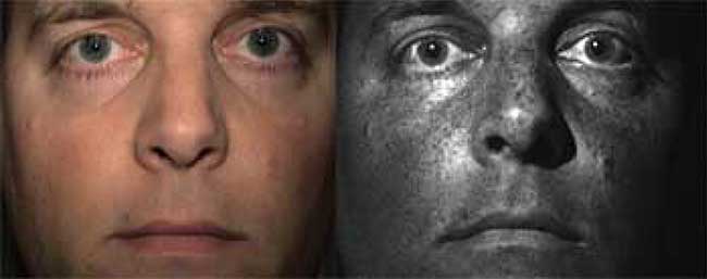
Figure 1. Photographs taken in the visible- and near-UV bands. Left: color, right: near-UV.
For the purposes of this discussion, it is convenient to break the UV spectrum into two categories. We will define the near-UV waveband as 300 to 400 nm. Imaging in this band can be accomplished using sunlight for illumination; glass optics (lenses, windows, filters) can be used as well. We will define the shortwave-UV band as 200 to 300 nm. There is little to no sunlight at sea level in this waveband, so photographs must be taken with the aid of artificial light sources such as mercury lamps. Furthermore, conventional BK-7 glass does not transmit in this band, so fused silica or calcium fluoride optics is required.
Standard black-and-white film has plenty of UV response from about 250 to 400 nm. It must be used in conjunction with a barrier filter that blocks visible light while transmitting in the desired UV band. Images taken with black-and-white film and a SCHOTT UG-1 filter will be almost purely near-UV in content, as long as there is sufficient near-UV light available. UG-1 filter glass has a secondary transmission peak at 750 nm known as a red leak. Since black-and-white film is quite insensitive to light at these wavelengths and longer, the effect of the red leak on film is negligible. For digital UV photography, it is a serious problem and has resulted in both professionals and amateurs publishing near-UV images that are highly contaminated with red or near-IR content. It is possible to take shortwave UV images at 254 nm using a low-pressure mercury lamp and a special bandpass filter on a film camera equipped with shortwave-UV optics.
The problem with using a barrier filter on a single-lens reflex (SLR) camera is that the photographer cannot compose the shot with the filter in place. The UV focus is different from the visible-light focus point, so images may be blurry. The camera has to be prefocused by eye before the filter goes on the lens, and high f/stop settings are used to increase the depth of field. The combination of a filter that blocks the majority of sunlight and a high f/stop setting means that long exposures are required, even with relatively fast film. The awkwardness of photographing UV scenes with film is such that the method is not very widely used or written about.
Electronic imaging in the UV band
As the world transitions to digital imaging, invisible-light photography has followed suit. Photographers have converted standard color digital cameras to the near-infrared band (750 to 1100 nm). The conversion is generally straightforward, because the silicon sensors in the cameras are already responsive to near-infrared light, which means that manufacturers of standard color digital cameras have to install a filter to block near-IR to maintain correct color balance. In the aftermarket conversion, the near-IR blocking filter is removed, which allows near-IR light to reach the sensor. Then a barrier filter placed over the lens or sensor is used to block any visible light, resulting in digital images that are pure near-infrared. Some cameras converted in this manner can give a continuous live preview in the near-IR band, and automatically adjust the exposure and focus, even with the near-infrared barrier filter in place, making near-IR digital photography very easy.
Applying these same concepts to digital imaging in the near-UV is problematic because conventional silicon CCDs and CMOS detectors have a great deal of response at wavelengths of 700 nm and longer, but relatively little response in the near-UV band and virtually no response below 300 nm. In the case of commercial digital cameras, the situation is even worse, because the imaging sensor itself almost always has a UV blocking layer built into the sensor package window. Trying to push sufficient near-UV light through that layer can be difficult and requires long exposure times. Even though the near-UV content of the scene imaged on the sensor may be many times greater than the red and near-infrared content, the latter dominates the resulting image. The answer to this problem is twofold. First, one must use a CCD or CMOS sensor that does not have a UV-blocking filter built into either the sensor window or the antireflection coating on the sensor itself. Second, the filter used to block all but the near-UV radiation must not have a significant red leak.
There are various manufacturers offering UV-sensitive CCD cameras. There is a fairly large spread in price, from low-cost machine-vision UV cameras up to scientific-grade products. Some of these cameras have back-thinned CCDs, whereby the silicon substrate is thinned down to prevent it from absorbing UV radiation before the photodiodes on the back-side can generate carriers that result in photocurrent. The back-thinned CCDs are responsive down to 200 nm, and can thus be used for shortwave UV imaging, provided that the signal is strong enough. Some shortwave UV applications use image intensifiers with UV-sensitive photocathodes to detect the generally very weak signal from sources such as electrical corona discharge on power lines. A common back-thinned CCD camera used for shortwave UV imaging is the Sony XCD-SX910UV camera. This 2-megapixel camera takes frames at 15 Hz. The spectral response is shown in Figure 2. It can be used to take excellent near-UV images with glass lenses and high-quality barrier filters, as well as shortwave-UV pictures in combination with mercury lamp illumination.
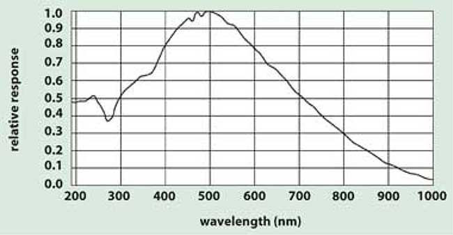
Figure 2. Spectral response normalized to the peak.
Recently, Fuji came out with a variation on its popular S-3 digital SLR camera. This camera, called the S-3 UVIR, is designed to be responsive from 380 nm to about 1100 nm, so that it can be used for UV and near-IR imaging. After extensive testing at the Brooks Institute of Photography, it was found that it has relatively little near-UV response when used in conjunction with filters that pass UV light in the 330 to 380 nm band. This is probably due to the presence of thin-film Bayer filters that are deposited directly onto the sensor. The ideal digital SLR for near-IR and near-UV imaging would not have these color filters, but since they are deposited at a relatively early stage of sensor fabrication, it is unlikely that Fuji or anyone else will be able to eliminate them.
Ultraviolet filters
One commercially available filter used in conjunction with silicon imaging sensors for near-UV imaging is the Baader Venus filter. This filter is used by astronomers to photograph cloud patterns in the Venusian atmosphere. The clouds are sulfuric acid, which is strongly absorbing in the UV band, so a great deal of contrast appears in these photographs. The Baader has an extremely small red leak, which is less than 0.1 percent of the peak transmission at 360 nm, and is better suited for use with silicon sensors than SCHOTT UG-1. It is also possible to use filters with red leaks as long as the leak is plugged by the use of a second filter. The second filter, typically made of blue glass, will reduce the red leak without destroying the UV transmission.
To create pure near-UV images without the use of a barrier filter the illumination source must be rich in ultraviolet radiation with as little visible- or near-infrared light as possible and ambient light must be reduced to or near zero. If reflected UV images are desired, it is critical that the scene or object not be fluorescent to any great extent, since the fluorescence signal will reach the sensor in the absence of a visible-light barrier filter.
Newport Corporation has a line of UV bandpass filters that are suitable for imaging in various bands of the UV. These filters typically have a small red leak that is less than 5 x 10⁻³. They can be used in combination with mercury lamps to produce very spectrally pure shortwave UV images.
Ultraviolet light sources
Most UV imaging applications require an external source of UV illumination, unless the object of interest is something like a laser beam, a high-temperature flame, or a high-voltage corona discharge that generates its own UV radiation. The most common UV illumination sources used for imaging include direct sunlight, gas discharge lamps and ultraviolet LEDs.
The solar spectrum is rich in near-UV light because of the very high temperature of the solar photosphere. The atmosphere has fairly high transmission in the visible band, but begins to cut off radiation below 400 nm, with a hard cut-off at 300 nm due to the ozone layer. For many near-UV imaging applications, direct sunlight is an excellent UV source, but for shortwave-UV applications, artificial lighting is required.
There isn’t much near-UV light indoors, since most modern window glass is designed with UV-blocking coatings. Indoor near-UV applications require something other than conventional incandescent or fluorescent lights, because they are generally designed to minimize near-UV which fades wallpaper and fabrics and isn’t used for human vision. The standard for artificial near-UV sources has historically been the mercury gas discharge tube. Mercury has a strong spectral line (known as the i-Line) at 365 nm. This is a very useful wavelength for many near-UV imaging applications, more so than 396 nm near-UV LED lights, for example. The kind of phenomena associated with UV imaging generally improve as wavelength decreases, and there can be marked differences in the appearance of subjects between 396 and 365 nm, though it is only a 31 nm wavelength difference. There are also mercury lines at 254 and 306 nm that can be used for illumination in shortwave-UV applications.
The black light mercury discharge lamps are coated internally with a filter material that appears nearly black to the eye. This filter is like a Woods’ glass in that it blocks visible light while transmitting UV light. It should be noted that there is a red leak in these filter coatings which makes the lamps unsuitable for use with silicon-based imaging sensors unless a barrier filter is used. The 254 and 306 nm lamps are built around uncoated fused silica tubes. These lamps are used for germicidal applications and are therefore relatively inexpensive. The low-pressure mercury lamps in particular are very spectrally pure, since the 254 nm line dominates over the other lines by a factor of 100 in brightness. Because the lamp pressure is low, the lines are exceedingly narrow because of the absence of pressure broadening effects.
Xenon lamps have an extremely high color temperature (>10,000 K) and generate substantial quantities of near-UV radiation. They are used in some UV light sources in conjunction with a Woods’ glass filter. The short-arc xenon lamps can be used to produce a directed beam of light with suitable optics since the light is emitted within a tiny volume, typically about a cubic millimeter. Deuterium discharge lamps are another commonly used UV source, though their emission spectra are quite broad. All will produce radiation below the glass cut-off at 300 nm. Since that radiation is fairly harmful, it may be advisable to block it using an uncoated BK-7 glass window for near-UV imaging applications.
Ultraviolet LEDs
In the last few years, UV LEDs based on gallium nitride semiconductor alloys have emerged as a very serious challenge to gas discharge lamps. These devices have many advantages over gas discharge lamps: spectral purity, long lifetimes, high beam intensities, shock and vibration resistance, and high-voltage power supplies are not required.
Manufacturers are developing ever-brighter LEDs at ever-shorter wavelengths. The LEDs are very spectrally pure and emit radiation out of a very small surface area. LED arrays are commercially available, and can be made to form well-collimated beams of UV light. Some of the smaller UV LEDs come encapsulated in plastic packages that have lens geometries molded in, as is the case with many standard visible light LEDs. Forming a tightly focused beam is difficult with cylindrical lamp sources.
The Nichia Chemical Corp. has a powerful LED that operates at 365 nm, which is the i-line of mercury vapor. The LED has a very narrow emission spectrum (8 nm FWHM) and current power levels are 200 mW out of a single device.
There are a few LEDs operating in the shortwave UV band but their power levels are very low and they are expensive. For now, low pressure mercury discharge lamps appear to be the best all-around source of light below 300 nm for shortwave UV imaging applications.
Ultraviolet optics
Standard glass optics does not perform well below about 320 nm. The glass BK-7, for example, has a 70 percent transmission point at about 325 nm in a 1 mm thickness. In a 3 mm thickness, the transmission drops to 34 percent. Below 325 nm, the transmission drops very rapidly to essentially zero by 280 nm or so. However, fused silica (often referred to as quartz) transmits quite well down to about 250 nm, making it a nice lens and window material for UV imaging systems, although it is difficult to shape because of its hardness. Special lenses created specifically for UV imaging have been made of materials like fused silica and calcium fluorite built into achromats.
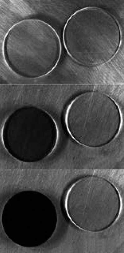
Figure 3. BK-7 window (left) and fused silica window (right) imaged in three UV bands. Photos courtesy of David Hayes.
Conventional wisdom is that if one is doing any kind of UV imaging, one must use fused silica optics. While it is true that fused silica optics have certain advantages over glass, they are much more expensive and are often not required for near-UV imaging in the 330- to 400-nm band, especially for imaging between 360 and 400 nm. Certain glass-based color video lenses work quite well and are only several hundred dollars. These lenses have about a 50 percent transmission in the near-UV band, which is 1 f/stop, and produce decent quality images. By using fast lenses, one can easily gain back the 1 stop. Fused silica lenses are required for imaging below about 320 nm, since conventional glass lenses absorb significant amounts of light below that wavelength, as shown in Figure 3. This series of images show a BK-7 window and a fused silica window sitting on a substrate of sanded aluminum which acts as an effective diffuse reflector. The BK-7 darkens at 306 nm and becomes completely opaque at 254 nm.
Near-UV imaging applications
The applications for UV imaging can be broken down into three main categories of phenomenology: absorption effects, scattering effects and the imaging of UV light sources.
UV absorption
Most near-UV imaging applications exploit the fact that near-UV light tends to be absorbed more readily than visible or near-infrared light. The higher energy of near-UV photons results in more direct interactions of the photons with electrons in materials. This can lead to stronger absorption relative to visible and near-IR light.
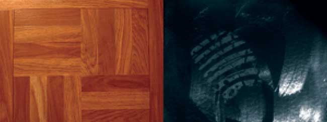
Figure 4. A vinyl floor tile coated with wax shows a shoe impression. The color image shows only a trace of the print against the tile’s pattern (left). In the near-UV image, the wax is no longer transparent and the lines and swirl patterns left by the cloth applicator dominate the image, except where the shoe impression has flattened out the swirl marks.
Indeed, one of the first things one notes when observing everyday objects in the UV band is how dark things look. This higher absorption also means that one tends to see the outermost layers of objects that may be slightly translucent at longer wavelengths. For many materials – especially organic materials – the shorter the wavelength of incident light, the stronger the absorption and the shallower the depth of penetration.
The absorption effect can lead to the detection of thin layers of visibly-transparent substances on a substrate and their surface texture (Figure 4).
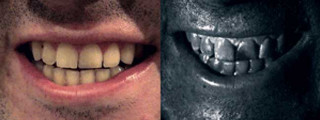
Figure 5. A left incisor repaired with dental resin. Left: color, right: near-UV.
The teeth shown in Figure 5 are real, but the left incisor has been repaired with a composite resin. The resin is strongly absorbing in the near-UV band, and the absorption effect gets stronger as the wavelength gets shorter. Normal tooth material is inorganic, and tends to reflect near-UV readily due to Fresnel reflection at the interface between air and the microcrystals of hydroxyapatite, the mineral that constitutes tooth enamel.
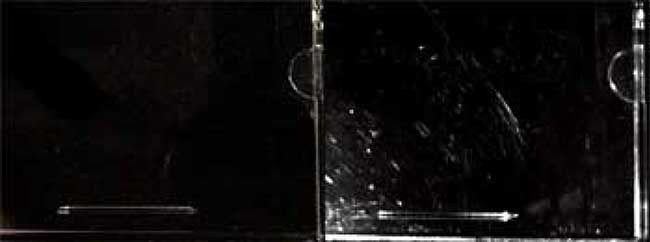
Figure 6. A CD jewel case with scratches that scatter near-UV light much more than visible light. Left: color, right: near-UV.
Wave scattering effects
Another class of applications exploits the short wavelength of near-UV light and the reflection of light off surfaces. Lightwaves tend to scatter off of surface features that are comparable in size to or larger than a wavelength of the light. This means when illuminating a surface with near-UV light and imaging the reflection with a near-UV camera, there will tend to be stronger scattering off of surface anomalies such as scratches and digs than what one observes with a visible-light camera. A piece of metal polished with steel wool will have a dull finish to it when examined by eye. In the near-IR band the same piece often will appear to be a perfect mirror. The scratches in the surface are smaller than a wavelength of infrared light, but larger than a wavelength of visible light (~0.5 microns). This same effect works in reverse for shorter wavelengths. A piece of smooth plastic, like a CD jewel case, may appear very polished to the eye. When the same surface is viewed with a near-UV imaging system, numerous small scratches appear, as shown in Figure 6. This effect carries down into the shortwave UV band as well, and some manufacturers of precision glass optics use shortwave UV systems to check the polish on their products.
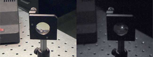
Figure 7. A slightly burned lens with 355 nm laser energy scattering off the burn mark. Left: color, right: near-UV.
Ultraviolet light sources
A third class of applications is the imaging of UV sources. In many applications where UV light is used, it is not necessary to directly image the UV light source. For example, in Figure 7, the lens in the lens holder is transmitting an ultraviolet laser beam, a frequency-tripled YAG laser operating at 355 nm. The operator can verify the presence of UV light in the system by placing a standard business card in the optical path. The UV light makes the card stock glow, since it has been treated with fluorescent optical brighteners. But in this particular instance, the lens has been burned by excessive laser intensities. The burn mark acts as a diffuser, bleeding laser energy in all directions. A UV camera system can see that effect in a way that would be impossible to reproduce with a fluorescent card.
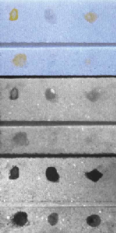
Figure 8. A marble tile with egg proteins imaged in three bands. The left dots are yolk, the middle pure white and the right is uncooked scrambled egg.
Shortwave-UV imaging applications
The applications for imaging below 300 nm are similar to the near-UV applications already discussed. What is generally observed is that phenomena that manifest in the near-UV band tend to get more pronounced in the shortwave-UV band. For example, Figure 8 shows a white marble tile with dots of egg yolk, egg white and scrambled egg on it (left to right). The top row of dots is the same as the bottom, except that the bottom row consists of thinner layers. This is a test coupon that simulates a marble statue with egg-based paint residue on it. Apparently, reflected-UV imaging has been used to look for traces of ancient pigment on statuary from classical antiquity.
The 254 nm image shows much more pronounced absorption by the egg proteins relative to the 365 nm band or visible images. The same effect applies to almost any organic trace material deposited on a substrate with a different degree of reflectance than the trace.
Another example of contrast enhancement being sensitive to wavelength is shown in Figure 9. This is a mosaic of four images of a plastic sample container with SPF30 sunblock in it. The 310 nm image is remarkable because some small smudges of sunblock on the inside of the lid are apparent. The 254 nm image shows the smudges too, but with less contrast, as the plastic absorbs fairly strongly at this wavelength. It is evident that one can have too much of a good thing and that shorter wavelengths of UV do not always increase contrast, particularly if the target of interest is an organic trace material on an organic substrate.
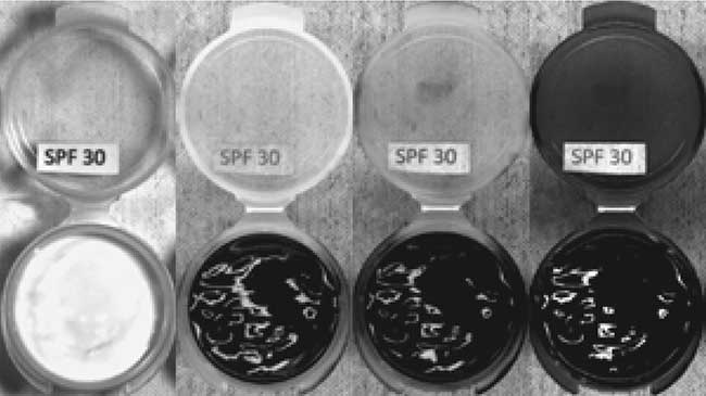
Figure 9. Four images of a plastic sample container with SPF30 sun block in it. Note the smudge on the inside of the lid in the 310 nm image.
Conclusion
It is instructive to summarize the findings described above as rules of thumb to help guide investigations into UV imaging:
• Of the three common imaging bands used in film or digital-based photography, UV light tends to be absorbed by materials to the greatest extent relative to visible or near-infrared light.
• Digital sensors have effectively displaced film for UV imaging in both the near- and shortwave-UV bands, but they require careful control of any out-of-band light (particularly in the red part of the visible spectrum) to be effective.
• Special optics for UV imaging is required to work below about 320 nm, but glass lenses will work satisfactorily for near-UV work.
• The solar spectrum at sea level contains plenty of near-UV light (300 to 400 nm) for imaging, but virtually no shortwave-UV light (below 300 nm). Therefore outdoor imaging using reflected sunlight is possible in the near-UV band, but shortwave-UV imaging requires an active illumination source.
• Indoor UV imaging requires specialty UV light sources, as there is very little UV in indoor spaces by design.
• LED-based light sources are displacing gas-discharge tubes in many near-UV applications, but tubes filled with mercury vapor are still the best choice for shortwave-UV imaging illumination.
• Organic materials tend to absorb UV more strongly than inorganics. Thus, a scene with organic material on an inorganic substrate (and vice-versa) will tend to show more contrast in the UV than in the visible or near-IR bands.
• The organic versus inorganic contrast effect described above tends to increase with decreasing wavelength down to 254 nm. Below that wavelength, light sources and optics become rapidly more expensive and impractical for imaging.