Determining LED size during the design phase indicates the resulting display luminance, efficiency and power requirements.
Dr. Martin Kykta, Uni-Pixel Displays Inc.
A time multiplexed optical shutter display is an optical system that uses a thin polymeric film as a light valve to locally manipulate the phenomenon of total internal reflection at each pixel. The light valve is a deformable membrane with a micro-optical layer that contacts a clear and flat total internal reflection lightguide. The membrane covers the lightguide and is a microelectromechanical system (MEMS) (Figure 1). When the micro-optical layer on the membrane touches the lightguide surface, total internal reflection light escapes (Figure 2). Red, green and blue light is rapidly and sequentially strobed into the lightguide from the edge using appropriately configured sources.
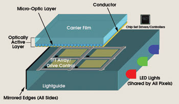
Figure 1. In this 3-D view of four pixels of a time multiplexed optical shutter display (not shown to scale), the LEDs are coupled into the lightguide at the edge. TFT = thin-film transistor.
The primary light sources for these displays are LEDs, which are the obvious choice because the design for the time multiplexed optical shutter display is driven by the desire for brightness, power efficiency and a compact size. Questions do remain, however, including how many LEDs are needed to achieve a given luminance, how efficient are the LEDs, and how much power will they require?
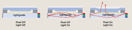
Figure 2. This is a simulated view of a working time multiplexed optical shutter display. Light is injected into the lightguide by the LEDs located on the edge and is trapped by total internal reflection. The light escapes when the micro-optical layer on the membrane touches the lightguide surface.
The key to answering these questions lies in the choice of LED size.
The largest commercially available LEDs that provide sufficient lumens and that are small enough to couple to the lightguide edge typically have a surface area of 300 × 300 μm2. Blue, green and red LEDs are usually packaged together as a white-light system by manufacturers and are binned into various intensity categories.
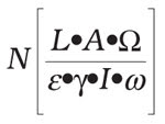
The total number, N, of LEDs required to illuminate a display depends on a number of factors, including the surface area, A; the desired white luminance, L; the viewing angle, Ω; and the display efficiency, γ (which is related to losses within the display). The relevant LED factors are: the maximum white intensity, I; the emission angle, ω; and the light insertion efficiency, ε. The total number of white LEDs needed (where one blue, one green and one red LED make up one white LED) is given in the following equation:
If the display and LED are lambertian emitters, then the viewing angle, ½, and the emission angle, ω, are equal to π steradians and cancel out. The intensity of each LED color required to produce a correlated color temperature equaling 6500 K white depends on the spectrum of each color LED. Typical LED peak wavelengths for blue, green and red are 464, 522 and 638 nm, respectively. If the spectra have normal widths, the required relative photometric proportions for blue, green and red are 0.0764 to 0.6574 to 0.2661. Therefore, to achieve 6500 K white, these relative proportions must be preserved. If the maximum green intensity ratio is 1.046 color density at 20 mA, then blue and red intensities must be 0.121 and 0.423 color densities, respectively. The white intensity sum is 1.59 color density.
To calculate the number of LEDs required for a small display size, say 80 × 60 mm, assume that the LEDs and the display are lambertian emitters and that the light insertion efficiency is 0.92 and the display efficiency is 0.61. Also assume that the desired display white output is 560 nits and the LED white intensity sum is 1.59 color density. The number of packaged white LEDs is calculated as follows (cd = color density):
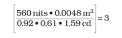
The above calculation shows that three white LEDs — or three each of blue, green and red LEDs — are necessary to achieve a time multiplexed optical shutter display that produces a 560-nit white to provide a correlated color temperature equal to 6500 K. Unfortunately, the green intensity and 1.046 color density required for this display are in the top two bins shipped by the manufacturer. A typical green intensity may be one-half as much, or 0.523 color density. The intensities for the blue and red LED shipped in the same package are 0.121 and 0.423 color densities, respectively, at 20 mA. If the LEDs are to be driven at the same current to produce a correlated color temperature white of 6500 K, four LEDs are needed in a package: two green, one red and one blue. If the LEDs can be driven at different currents, the green will have to be driven at more than twice the current of the red and blue LEDs because green LED efficiency drops off at higher current density and is not as good as the blue and red efficiencies.
Good LED performance requires good heat sinking and, typically, these small white LED packages are not designed for good heat conduction, and the LED die do not have good current spreading. Also, product specification sheets can be misleading. For example, the green LED in the typical white package is rated at 42 lm/W at 20 mA in the specification sheet. This number applies only to parts that come from the top intensity bin. Similar ratings for blue and red are 15 and 34 lm/W, respectively. In reality, measured values for average bins of green, blue and red are 21.9, 6.4 and 28.7 lm/W, respectively. It would be ideal if manufacturers could provide a white-balanced package, which may entail including two green die rather than only one.

Let’s examine the measurements that support these claims, which can be investigated using an integrating sphere with a spectroradiometer, a power supply and a volt-ohm-amp meter. The small LED devices were tested from 0 to 80 mA, which is above their rated current handling of 50 mA for blue and green and of 70 mA for red. This was done to make the point that small LED devices are not performing at levels reported for the large LEDs (1 × 1 mm2) operated at higher current densities. The wall-plug efficiency for the large blue LEDs has been reported by Osram Opto Semiconductors GmbH of Regensburg, Germany, to be as high as 56 percent at low currents and as low as 29 percent at high currents. A small blue LED (0.290 × 0.290 mm2) tested below had a wall-plug efficiency of 12 percent at low currents and of 5 percent at high currents.
The lumen output for the green and the red LEDs is similar (Figure 3). This indicates that the red LED is very efficient and that the green is not. The red LED luminous efficacy is 165 lm/W and the green, 512, at 10 mA. These numbers indicate that the eye is three times more sensitive to detecting green than red because green is closer to the peak efficiency (683 lm/W) of the luminous curve at 555 nm. The red LED must be at least three times more efficient than the green to match the lumen output.
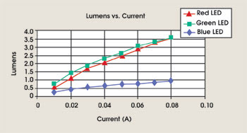
Figure 3. In this graph of lumens vs. current for blue, green and red LEDs, the lumen output for the green and the red LED is similar, indicating that the red LED is very efficient and that the green is not.
The measured wall-plug efficiency of the red LED is close to 18 percent, whereas the green is only 5 percent and the blue, 11.5 percent at 10 mA (Figure 4). The efficiency of LEDs is best at low currents and drops off as the current increases. The falloff in efficiency can be from 25 to 50 percent, depending on the LED color.
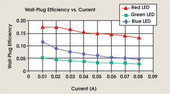
Figure 4. At low currents, the efficiency of the red LED is best (18 percent), and the green is worst (5 percent).
As with wall-plug efficiency, the luminous output per watt of electrical power or luminous efficiency (Figure 5) shows a similar decrease when going from low to high current. The reported values on the manufacture’s specification sheet for blue, green and red are 15, 42 and 34 lm/W, respectively. The actual values are 6.4, 21.9 and 28.7 at 20 mA, and they decrease significantly at high currents.
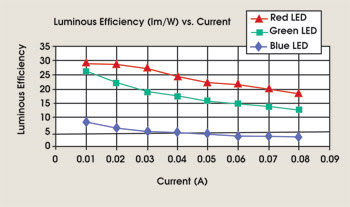
Figure 5. The blue, green and red luminous efficiency is lower than reported by the manufacturer.
The peak wavelength of a LED shifts when changing the drive current from low to high. The peak wavelength shift indicates that the LED’s color is shifting slightly. This shift in color can be seen when examining the luminous efficacy of the blue, green and red LEDs (Figure 6) at low and high currents. All curves show that there is a decrease in luminous efficacy (the ratio of visible lumens per radiant watts produced). The green and blue shift toward the shorter wavelengths at higher currents, while the red shifts toward the longer wavelengths, causing all the curves to decrease in luminance efficacy at higher current.
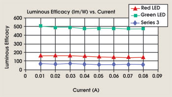
Figure 6. Here the wavelength shifts at high currents. All curves show that there is a decrease in luminous efficacy. The green and blue shift toward the shorter wavelengths at higher currents, while the red shifts toward the longer wavelengths, causing all the curves to decrease in luminance efficacy at higher current.
Because the color shifts are different for each LED, the ratio for combining blue, green and red to make white is different at low and high driving currents.
The electrical power consumption of the green and blue LEDs is similar, whereas that of the red is much less (Figure 7). It is expected that red LEDs use less power because red light is more energetic than blue. The fact that blue and green LEDs consume that same power even though blue light is more energetic than green is another indication of green LED performance and low efficiency.
Figure 7. The electrical power consumption of the blue and green LEDs are similar and larger than that of the red.
There is a need for a small LED die with performance characteristics comparable to the large dies currently used for lighting applications. Although small LEDs can be used to achieve the desired luminance, the efficiencies are approximately two to five times lower than can be achieved by larger LEDs.
A short-term solution would be for manufacturers to supply a white-balanced package, including two green die if necessary. However, in the long term, highly efficient small LEDs are needed for a variety of applications, from cell phones to lighting. For small-form-factor LEDs, the current state of the art can be significantly improved.
Meet the author
Martin Kykta is a senior research scientist at Uni-Pixel Displays of The Woodlands, Texas; e-mail: [email protected].