Output measurements are enhanced with an understanding of the capabilities and limitations of available metrology instrumentation.
Dr. Hubert Kostal and Ron Rykowski, Radiant Imaging
LEDs have evolved rapidly from use as simple indicator lights to use in more complex arrays and assemblies for illumination, displays, instrument panels, projectors, backlights, and medical and scientific instrumentation. These more sophisticated applications are driving the need for increasingly stringent luminosity and chromaticity measurements. In a cell phone display, for example, the color and luminance must be uniform and must not degrade over time.
A clear difference exists between measuring LED performance in production and evaluating it in development. In particular, quality assurance and quality control during production place a priority on speed, cost and ease of use. There often is more than one way to obtain these types of measurements, and choosing the optimum solution for a particular production situation requires a clear understanding of the type of data required and of the capabilities of the instrumentation used.
Photometers, colorimeters
Photometers and colorimeters measure light and color, respectively, as referenced to the response of the human visual system. In practice, a typical photometer consists of light-collection optics, a filter and a detector. The filter and detector combination is carefully designed to match the photopic luminosity function, which, as defined by the International Commission on Illumination (CIE), mimics the luminance response of the human eye. Colorimeters for measuring light source output (as opposed to those intended for measuring surfaces) use light-collection optics and a set of three filters and detectors. The responses of the three filter-detector combinations are set to replicate each of the three CIE color-matching functions.
Photometers and colorimeters can take measurements rapidly and are low in cost and easy to use. However, these instruments measure only a single spot at a time. Therefore, they cannot produce spatially resolved data unless multiple individual measurements are combined. It is time-consuming and labor-intensive to record and combine a series of measurements manually; therefore, an instrument that takes all the measurements at once is preferred. They are useful, however, for tasks such as quick measurement of LED color coordinates. In this case, the colorimeter is simply pointed directly at the LED, and a measurement is taken. Sometimes measurements are taken from several angles to obtain a crude estimate of variation in color as a function of angle.
Integrating sphere
The integrating sphere is used in conjunction with a photometer or spectrometer to enable accurate measurement of the entire output distribution of a light source. It is a hollow sphere whose inner surface has a diffuse, high-reflectance coating. Source light is introduced through an entrance port, and multiple reflections from the inner surface of the sphere cause this input to become highly homogenized. Output then is measured at an exit port.
Because all spatial information is lost with an integrating sphere, the devices are most useful for measuring total luminous flux, integrated spectrum and integrated chromaticity coordinates. The main advantages of the integrating sphere are rapid measurement speed and low cost. Typical applications for an integrating sphere would be measuring total luminous flux and binning of LEDs for dominant wavelength. They cannot directly provide information on luminance, luminous intensity or color as a function of angle, which is a serious shortcoming when directionality is important.
Imaging colorimeter
The imaging photometer or colorimeter was developed to enable accurate, spatially resolved measurements of color and luminance. Conceptually, the instrument is like a spot photometer or colorimeter, except that the single detector is replaced with a CCD, so that luminance or color data can be obtained for every pixel in the image. This is equivalent to taking on the order of one million linked measurements simultaneously.
The main components of an imaging colorimeter are an imaging lens, a set of color filters, a CCD detector, and data acquisition and image processing hardware/software (Figure 1). Other elements may include neutral density filters or a mechanical shutter.
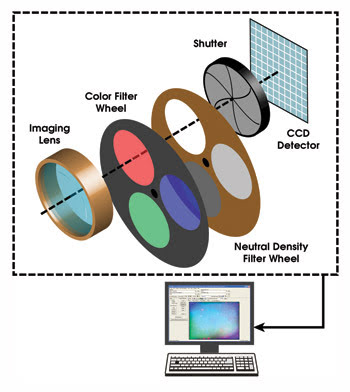
Figure 1. To perform colorimetric measurements, an imaging colorimeter acquires an image of the illuminance pattern under test through each of the various color filters. The neutral density filters are employed as necessary to ensure that each color measurement uses the full dynamic range of the sensor. Photometric measurements are performed using only the green (photopic) filter.
A typical application for an imaging colorimeter would be obtaining the entire illuminance distribution of an LED-based luminaire in a single measurement. This is accomplished by acquiring an image of the luminaire’s illumination pattern on a screen. The imaging colorimeter also excels at measuring uniformity of extended sources, such as gauging the luminance or color uniformity of an entire LED-based display backlight assembly. The instrument even can be used to automatically identify small defects (e.g., dark spots). And it can be used to examine LED signs or arrays; in this case, the imaging colorimeter can measure color and luminance simultaneously for each individual emitter in the product.
The primary advantage of imaging colorimeters and photometers is their ability to acquire multiple data points in a single measurement, making them inherently faster than any approach based on spot measurements. Furthermore, these instruments acquire a much more complete data set than can be obtained with a series of spot measurements, which makes it easier to identify localized variations in luminance or in color characteristics. Therefore, their slower measurement speed and higher cost are offset by the volume of data generated.
Imaging sphere
The imaging sphere is an optical system used in conjunction with an imaging photometer or colorimeter to acquire in a single measurement the entire far-field luminous intensity distribution of an LED. The optical path of the imaging sphere includes a coated, diffuse, low-reflectance hemisphere, a curved secondary mirror, and a CCD-based imaging photometer or colorimeter.
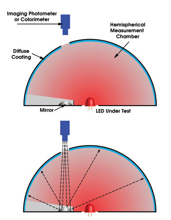
Figure 2. In an imaging sphere, an LED under test illuminates virtually the entire inner surface of the imaging sphere. During measurement, the mirror acts as a fish-eye lens, enabling the camera to view the entire inner surface of the imaging sphere and to capture 2π sr of source output in a single exposure.
In operation, the LED being tested is positioned through the aperture into the hemispherical chamber. Light from the LED strikes the inner surface of the coated hemisphere, which is essentially a curved screen. The convex mirror at the base of the chamber acts as a “fish-eye lens,” enabling the camera to image the entire inner surface of the hemisphere in a single exposure.
This image contains all the information necessary to reconstruct the angular intensity profile of the illumination over nearly 2π sr. The angular resolution of the instrument is determined by the camera’s image sensor and typically is <0.5°. The entire instrument is contained in a lighttight enclosure, enabling its use in production environments with high levels of ambient light.
The other major component of the imaging sphere is a PC-based software application that controls all camera functions, acquires image data, and factors in corrections based on various previously performed calibrations. The software also may be used to control other parts-handling equipment to more fully automate testing and to integrate the system with other equipment in the production line.
The advantage of the imaging sphere is its ability to acquire angularly resolved color and luminance intensity data for the entire output distribution of an LED in a single measurement, taking just a few seconds. For many applications, this detailed information is important enough to justify the additional cost of the system.
In conclusion, advanced LED-based products place stringent requirements on source performance. Manufacturers, therefore, need instrumentation that can deliver quantitative measurements of LED output and that can be used to implement uniform and objective standards throughout the supply chain. Table 1 summarizes the most common production LED measurement tasks and the optimum instrument to be used for each.
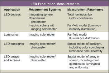
Table 1. Summarized above are the typical production measurement tasks required for several types of LED-based products and identifies the optimum instrument for performing each.
Meet the authors
Hubert Kostal is vice president of sales and marketing, and Ron Rykowski is president and chief technology officer, at Radiant Imaging in Duvall, Wash.; e-mail: [email protected].