Although the test method is a fairly straightforward source/measure test, implementing it in high-power LED lighting circuits presents significant challenges for both the source and the measure instruments. The source instrument must deliver fast and precise high-current pulses into a circuit of high-power LEDs and wiring and then recover rapidly to low current levels to enable accurate measurement of junction bias voltages. Pulse currents up to 10 A are typical (and increasing) with hundreds of volts of compliance, and the low currents are three to five orders of magnitude below these levels. Similarly, the measuring instrument must recover quickly from high common-mode voltages (up to 200 V) to make a millivolt-accuracy measurement in tens of microseconds after a trigger event.
To meet these requirements, custom approaches using data-acquisition systems and pulsed sources sometimes are tried, but data-acquisition devices have limited common-mode voltage capability. These requirements also are beyond most source meters, which are the instruments often used for this type of measurement.
To measure the junction temperature in high-power LED applications, it is best to separate the source and measure functions so the optimal instrument can be selected for each function.
Selecting an instrument
Figure 1 shows an example of junction temperature measurement in a high-power lighting product that was performed with separate source and measure instrumentation. The device under test features a series circuit of several LEDs all mounted to a custom heat sink to remove waste heat. In this example, the junction temperature is measured for one LED in the array, and the thermal resistance (R
θ) from the junction to the case is calculated.
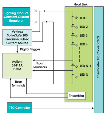
Figure 1. An example junction temperature measurement in a high-power solid-state lighting product is shown. A thermoelectric cooler maintains the heat sink at a controlled temperature during the K-factor calibration.
To achieve the precise pulsed current, the constant current regulator is replaced with a precision high-compliance pulsed source, which in this case is the SpikeSafe 200 from Vektrex Electronic Systems Inc. of San Diego. This instrument uses digital power technology to yield precise current pulses of any duty cycle at compliance voltages up to 200 V with precise low-current control between pulses.
The LED’s forward voltage must be measured with submillivolt accuracy after the high-current pulse, which is difficult when the overall circuit voltage can approach 200 V. The 34411A digital multimeter from Agilent Technologies Inc. of Santa Clara, Calif., was used because it is a high-speed sampling voltmeter with fast settling time and can make 20-μs aperture-triggered measurements. It also has high common-mode voltage rejection, allowing it to make a differential voltage measurement on a single LED with high offset voltage.
To make the specified measurement, the K-factor for the test LED is calculated first. This is achieved by driving the LED string with the (low) measuring current while controlling the heat sink temperature with a thermoelectric cooler. Because there is little self-heating with the measurement current, the junction temperature is assumed to be the same as the heat sink temperature. Precise temperature readings are obtained using the digital multimeter and a precision thermistor mounted to the heat sink near the LED.
Once the K-factor is calculated, the junction temperature is determined using the dynamic method’s pulsed current. Having the (high) heating current set to the lighting product’s nominal operating current simulates nominal operating conditions. To establish the starting temperature and voltage, a reference temperature and forward voltage measurement are taken with the measurement current first. Next, the LEDs are driven with the two-level pulsed current. The measurement level is the same as that used to obtain the K-factor (Figure 2). In this example, the current source is programmed to pulse down to the measurement level once per second and to remain at that level for 200 μs. The digital multimeter is configured to read a series of 20-μs samples and is triggered externally by a digital trigger.
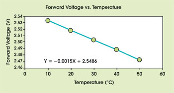
Figure 2. In this example of a typical curve, a K-factor of –1.5 mV/°C is observed. Similar devices often will have a similar K-factor.
The voltage sample (Figure 3) that is used to calculate ΔV is taken 140 μs after the trigger, allowing the circuit and the digital multimeter input time to settle after the high current pulse. This voltage and the K-factor are used to complete the calculation for the junction temperature. For the tested LED, the junction temperature was found to be 39.1 °C — 19.6° above the case temperature of 19.5 °C.
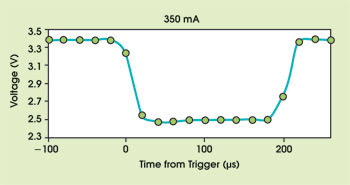
Figure 3. A plot of LED forward-voltage samples taken with a digital multimeter shows good flatness, indicating that little junction cooling occurred during the short measurement interval. It is critical that the power supply and the digital multimeter settle and measure accurately a few microseconds after the high current and voltage conditions.
Once the junction temperature is known, another important parameter, thermal resistance (R
θ), can be calculated. Thermal resistance is a value that quantifies the LED’s ability to transfer heat to its surrounding mount:
Rθ = ΔT/(Vf*If)
Using the junction temperature, the tested LED was calculated to have an R
θ of 16.6.
High-power applications
With the right instrumentation, it is possible to monitor accurately the junction temperature of an LED in challenging situations such as high-voltage lighting circuits. Besides thermal design of lighting devices, this technique can be used for other series-circuit applications, such as LED burn-in. Using a circuit similar to the example above, along with signal switching, one can construct a large-scale burn-in system with in situ junction temperature monitoring of every LED. In such a system, devices with improper thermal mounts can be identified and replaced before they overheat and fail.
The techniques outlined here are also useful for single-LED thermal characterization. Many LEDs now in development are slated to operate at currents and voltages well above the 5-W LEDs now in use — too high for most of today’s source/measuring instrumentation. The sampling digital multimeter/digital power current source combination provides a flexible way to power these devices and to measure junction temperature, allowing the semiconductor package to be tested and improved.
Meet the authors
Jeff Hulett is chief technology officer at Vektrex Electronic Systems Inc. in San Diego, and Chris Kelly is a design engineer at Agilent Technologies Inc. in Loveland, Colo.; e-mail:
[email protected];
[email protected].