New technology is changing x-ray imaging in dentistry.
Jennifer Weldon and John Gilmore, Hamamatsu Corp.
Recent advances in digital radiographic imaging technology are changing the practice of dentistry. Digital panoramic and intraoral imaging provide instant access to adjustable high-quality images with a lower radiation dosage than that required for traditional film imaging. In addition, the latest modality in dental imaging — cone-beam CT — provides dentists with immediate access to three-dimensional images of a patient’s mouth and jaw.
The rising adoption of digital x-ray technology is motivated by its three primary advantages over film-based image acquisition: It can speed work flow and provide better images, and it requires less radiation.
Digital technology speeds work flow by eliminating the need for film developing. A diagnostic image can be processed digitally and displayed on a computer screen within seconds after x-ray exposure. As a result, dentists can make diagnostic assessments right away or can recognize immediately the need to take another image. Furthermore, they no longer have to maintain a darkroom, so costs are reduced, and practices are operating more efficiently.
A digital image is adjustable in ways that a film image is not. Unlike conventional radiography, which results in permanent fixed images, digital software programs allow images to be maneuvered, enlarged and magnified for improved diagnostic assessment. Such flexibility also facilitates the explanation of this information to patients because, by viewing the images, they can better understand the dentist’s assessment.
Digital systems are safer than film because solid-state detectors require up to 50 percent less radiation than film does to obtain a properly exposed image. Images also can be easily duplicated without causing additional radiation exposure to patients. Additionally, film-based systems generate biohazardous waste products that harm the environment, and this alone has driven significant market change toward digital x-ray imaging.
Because of these advantages, dentists are rapidly incorporating this new technology into their practices. Of the estimated 200,000 dentists practicing in North America, about 30 percent use a digital x-ray system for image acquisition, and this figure is expected to rise rapidly. To encourage the conversion to digital technology, dental equipment manufacturers and distributors are offering financial and training options to offset the high cost of installing new equipment. This shift is not limited to dentists; veterinarians are quickly making the jump to digital as well (Figure 1).
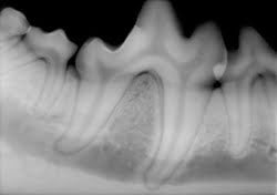
Figure 1. This intraoral x-ray image shows a dog’s teeth.
The standard care modality is intra-oral imaging. For this, digital image sensors are available in sizes 0, 1 and 2, which relate to the intraoral film sizes. Size 2 is most commonly used in North America for taking both vertical and horizontal bitewing images, which are used in all areas of dentistry to view small details of a patient’s oral cavity to detect early signs of oral cancer, gum disease, bone loss, impacted wisdom teeth and eruption of primary teeth.
CMOS and CCD
X-ray imaging sensors are composed of a scintillator that converts x-ray photons into visible light, as well as a CCD or CMOS detector. There are advantages to both types of sensors. CCDs tend to have fewer blemishes and less fixed-pattern noise than CMOS detectors. In some cases, this eliminates the need for defect mapping (image correction) and simplifies postprocessing of images. CMOS detectors, on the other hand, allow additional functionality (electronics) to be built onto the chip, reducing the amount of external support electronics and decreasing the computer interface box size and cost. It also is possible to design wireless intraoral sensors using CMOS technology. The trend in the dental market is transitioning from CCD to CMOS to reduce the need for external support electronics and to allow for more work space.
Cesium iodide or gadolinium oxysulfide scintillators can be used in image sensors. Cesium iodide is more efficient because it requires less x-ray radiation to produce an image. This material directs the light through a needlelike columnar structure that has relatively high light yield for better image quality. Gadolinium oxysulfide, on the other hand, is less expensive.
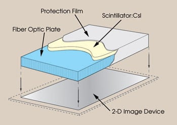
Figure 2. This image displays the fiber optic plate with the scintillator structure of an image sensor.
Sensors that have a fiber optic plate produce higher-quality images. The fiber optic plate directs the scintillator’s light onto the image sensor and prevents nonconverted x-rays from interacting directly with the image sensor (Figures 2, 3). Such direct interaction degrades image quality and creates white spots, commonly referred to as zingers.1

Figure 3. Cesium iodide scintillators have a needlelike structure.
A more comprehensive view of a patient’s mouth and jaw can be achieved with panoramic imaging. Dentists use this modality to look at the entire structure of a patient’s mouth and parts of the jaw in a single view. Panoramic imaging does not eliminate the need for a smaller view obtained from a traditional bitewing image; instead, it complements the intraoral image by enhancing the diagnostic evaluation of spatial relationships and tooth positions. Panoramic imaging now is being employed by orthodontists and endodontists, whereas in the past it was used mostly by general practitioners. Specialized software applications used with panoramic imaging offer an accurate view for treating dental implants, temporomandibular joint (TMJ) disorders and sinus infections and for making other dental assessments.
Unlike traditional intraoral x-rays, the panoramic x-ray rotates around a patient’s head and scans the entire jaw to provide a thorough image of the entire oral cavity. Within a minute, the entire process is completed, without causing patients any discomfort (Figure 4).
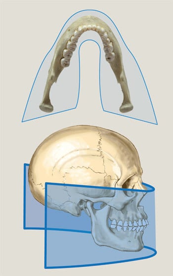
Figure 4. This image illustrates the continuous motion of the panoramic x-ray while it rotates around a patient’s head and scans the entire jaw.
Digital systems for panoramic imaging generally are based on a CCD imaging device or on photostimulable phosphor plates. With the latter, x-ray images are stored temporarily in the phosphor plate until they are read out by a scanner. This two-step process requires dental professionals to transfer the plates to a scanner after the examination.
Unlike conventional film, photostimulable phosphor plates are erased during the readout process — and thus are reusable — and the x-ray image is digitized into a computer.
A common CCD imaging readout technique for panoramic imaging is time-delay integration. This technique allows for continuous imaging and increases signal levels by synchronizing the readout of the CCD with the rotation of the x-ray generator. During the rotation, the sensor outputs a new row of information as it collects incoming data. This technique improves the sensitivity of the system, thereby lowering the patient’s radiation dose. The relationship between the CCD readout — known as clocking — and arm rotation must be matched precisely to prevent the image from blurring. More sophisticated systems vary the rotation speed according to the CCD signal strength. Thicker regions of the patient’s anatomy reduce the signal strength, thereby warranting slower rotation speeds to compensate.
Cone-beam imaging
The most advanced imaging technology on the dental market is cone-beam CT, which maintains advantages over panoramic and intraoral imaging because, unlike those modalities, it can capture 3-D color images of the entire head and the neck.
Since being introduced in 2001, this technology has been adopted mostly by dentists and oral surgeons for diagnosing and treating conditions related to implantology, maxillofacial surgery, orthodontic planning, and to TMJ and other dental conditions.
Traditionally, for clinical decisions, patients had to undergo a full CT scan, commonly referred to as a CAT scan, at a local hospital, during which they were exposed to large amounts of radiation. A traditional CAT scan involves a ring-shaped scanner with a detector that rotates 360° around the patient’s head. The patient is moved about 1 or 0.5 cm at a time. The scanner’s detector emits a fan of x-ray beams from all angles. This scan can last from 30 to 90 min.
In contrast, cone-beam CT emits a cone-shaped x-ray beam that captures a large area while requiring a minimal amount of radiation. In fact, it images with radiation dosages up to 15 times lower than those of conventional CT scans. The patient’s head is placed between an x-ray source and a detector that are about 180° apart. Within seconds, the machine rotates 360° around the patient’s head, rapidly capturing static images. The computer reassembles these images — or CT slices — into a secondary reconstruction that contains all the data acquired from the scan. This results in a 3-D image for dentists to view. Because the data is isotropic, the entire volume can be reoriented so that the patient’s atomic features are realigned.2 Within minutes, dentists can view accurate 3-D color images.
The data for cone-beam CT is acquired using either a CMOS flat panel, an amorphous flat panel or an x-ray imager intensifier. Each flat panel technology offers advantages and disadvantages (see table below). Amorphous flat panels suffer from image lag, leaving small amounts of information trapped in the detector. This reduces the useful operating range and decreases the image contrast for CT applications.
CMOS flat panels
CMOS flat panels offer superior resolution and high frame rates. They have no image lag, thereby enhancing their useful operating range for CT applications. Amorphous silicon flat panels offer a larger imaging area and high resolution, allowing medical professionals to see more of the patient’s anatomy.
An x-ray image intensifier coupled to a CCD is an older technology that produces slightly distorted images requiring enhanced software modifications. It limits the usable imaging area because of the distortion at the edges of the image.
Although the machine costs associated with cone-beam CT are high, the imaging capabilities are revolutionary. Dentists have been slow to adopt this imaging technique, remaining comfortable using digital intraoral and panoramic modalities. There is, however, a machine on the market with capabilities for both panoramic and cone-beam CT imaging — Planmeca’s Promax 3D (Figure 5).
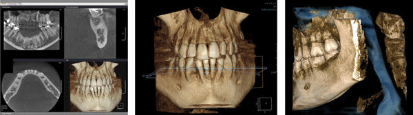
Figure 5. Cone-beam CT images for a proposed implant site are shown at left, a 3-D anterior view using Planmeca’s Promax 3D system is shown in the middle, and a 3-D lateral view using the same system is on the right.
Dr. Dale Miles, a diplomate of the American Board of Oral and Maxillofacial Radiology and the American Board of Medicine, educates dentists on cone-beam CT and uses the Promax. He believes that eventually everyone will be using digital technology.
Meet the authors
Jennifer Weldon is image sensor marketing assistant at Hamamatsu Corp. in Bridgewater, N.J.; e-mail: [email protected].
John Gilmore is MSEE image sensor marketing manager at Hamamatsu Corp.; e-mail: [email protected].
References
1. Sol M. Gruner et al (August 2002). Charge-coupled device area x-ray detectors. REVIEW OF SCIENTIFIC INSTRUMENTS, pp. 2815-2842.
2. William C. Scarfe et al (February 2006). Clinical applications of cone-beam computed tomography in dental practice. Journal of the Canadian Dental Association, pp. 75-80.