John Gilmore, Jennifer Weldon and Maridel Lares, Hamamatsu Corp.
The dental industry is continually changing, with more and more dentists adopting the latest
digital x-ray technology into their practices. The driving advantages of digital
x-ray systems versus film-based systems include the following: increased work flow,
high-quality x-ray images for improved diagnosis and reduced radiation exposure
for patients. Digital systems are based primarily on two sensor technologies: CMOS
(complementary metal oxide semiconductor) and CCD (charge-coupled device). This
article focuses on the key features and benefits of CMOS technology used in the
dental field.
Digital x-ray systems are used for three imaging modalities for dental diagnosis: intraoral,
panoramic and cone beam computed tomography (CBCT). Intraoral systems, used for
taking horizontal and vertical bitewings, provide dentists with detailed images
for enhanced diagnosis. Panoramic systems, which scan a patient’s entire mouth,
often use time delay integration (TDI) technology. CBCT equipment takes slices of
images, which are then reconstructed to form a three-dimensional image of a patient’s
entire jaw and mouth. These imaging systems use scintillators, which convert x-rays
into visible light, and solid-state sensors, such as a CMOS device, which detect
the scintillator’s emission.
A CMOS device converts light into a digital signal using photosensitive
pixels and on-chip circuitry. CMOS technology has a limited photosensitive area
and higher noise compared with a CCD, but the noise level has been improving. CMOS
has several useful characteristics: It requires low power to operate, has high-speed
readout, is capable of on-chip integration of electronic circuitry and produces
digital signals without external converters.
Cone beam computed tomography
CBCT, also known as cone beam volumetric tomography (CBVT) or
cone beam volumetric imaging (CBVI), generates 3-D images of the teeth and head
using x-rays and computer software. It was introduced in Europe and Asia in the
late 1990s, followed by its introduction in North America in 2001.
“The adoption is huge,” said Dr. Dale A. Miles, a
diplomate of the American Board of Oral and Maxillofacial Radiology. Miles, who
also analyzes cone beam computed tomography data from dentists across the nation,
said, “The early adopters [were] the orthodontists and oral and maxillofacial
surgeons. But periodontists and endodontists are jumping right in there big time,
especially because of the smaller field-of-view machines that have come out.”
Dental specialists and surgeons use the data from CBCT for placement
of dental implants, third-molar (wisdom teeth) extractions, TMJ (temporomandibular
joint) evaluations, orthodontic treatment planning, surgical planning and others.1
Each type of dentist requires a different CBCT field of view.
According to Miles, periodontists need a small field of view (6
x 6 or 8 x 8 cm) for implant placement. Endodontists need the same field of view
for implant surgery on failed endo teeth and a smaller one (4 x 4 cm) for root canal
therapy. For surgeons, an 8 x 8-cm field of view is sufficient for extractions,
but a larger one is needed for trauma cases and orthognathic surgery. Orthodontists
require the largest field of view to measure angles and lengths of anatomical landmarks
for treatment planning.
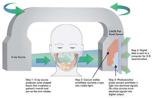
Figure 1. In cone beam computed
tomography, a cone-shaped x-ray beam irradiates a patient’s jaw. The transmitted
x-rays are detected by a sensor such as a CMOS flat panel sensor from Hamamatsu.
The data is sent to a computer and reconstructed into 3-D images by software.
Miles believes that CBCT will become the standard of care for
presurgical implant assessment and third-molar extraction. It is suited for such
imaging needs because of its accurate depictions of implant sites, its nondistorted
1:1 horizontal/vertical aspect display, and its ability to generate 2-D and 3-D
color images that aid the surgeon by showing the precise location of the inferior
alveolar nerve and other relevant structures.2
To generate 3-D images, a CBCT machine captures x-ray images of
a patient’s head, which computer software then reconstructs into a 3-D image
within a few minutes. In a CBCT machine, an x-ray source and a sensor are placed
180° apart on a rotating arm, and the patient is placed in the middle (Figure
1). CBCT uses a cone-shaped x-ray beam to acquire a volume of data at each frame,
generating a complete 3-D image (Figure 2) in one rotation or less. It requires
a much lower dose of radiation than medical computed tomography (CT), a benefit
to patients.
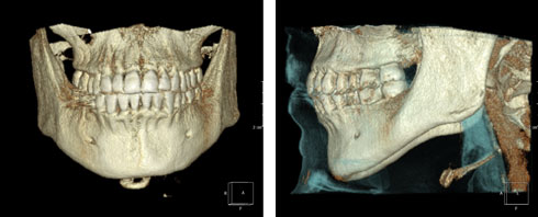
Figure 2. Three-dimensional
images created from a cone beam data set show teeth (left) and soft tissue outline
(right). The patient was imaged using Planmeca Oy’s ProMax3D CBVT machine
(Helsinki, Finland). Images were created in CyberMed International software called
OnDemand3D (Seoul, South Korea). Courtesy of Dr. Dale A. Miles.
The sensors used in CBCT machines are amorphous silicon (α-Si)
flat panels, CMOS flat panels or image intensifiers coupled to a CCD. CMOS flat
panel sensors have advantages and disadvantages compared with α-Si flat panels.
One advantage is smaller pixel size, resulting in higher resolution (Figure 3).
Also, unlike α-Si flat panels, CMOS flat panels do not suffer from image lag, a
residual charge left behind in the sensor that degrades overall image quality. It
is especially troublesome in CT applications because there is no time to correct
for it by reading the same exposure repeatedly until all the signal is read out
and summed and the pixels completely reset.
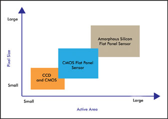
Figure 3. This is a general comparison
of pixel size and active area characteristics of CCD, CMOS flat-panel sensors and
amorphous silicon flat panel sensors.
A disadvantage of CMOS flat panel sensors is the size of the active
detection area. It is difficult to produce a single CMOS chip in a large size, unlike
α-Si flat panels. A common technique to overcome this issue is tiling multiple CMOS
chips to form a larger mosaic.
Amorphous silicon and CMOS flat panels are used in many of the
CBCT machines available today. These machines differ in field-of-view sizes, scanning
time, patient position (standing, seated or supine), software and other parameters.
They cost approximately $100,000 to $250,000, so many purchases typically are made
by multidentist clinics or imaging centers. However, dentists who don’t own
a machine can still benefit from CBCT images.
“Even if the dentist doesn’t buy a machine, [he or
she] can access the data from it,” Miles said. “That’s a big plus
for dentists. They don’t need to commit to a large capital outlay. They can
get the volume information in terms of the DICOM [Digital Imaging and Communications
in Medicine] data set, and put it in software to get out better data for their implant,
or for their orthodontic procedure or for a third-molar extraction.”
Panoramic imaging
Besides CBCT, panoramic imaging also uses CMOS technology. Dentists
use the panoramic mode to image the entire set of teeth and parts of the jaw in
a single view for placement of dental implants and assessment of TMJ disorders,
sinus infections and other problems. As with a CBCT machine, a panoramic machine
has an x-ray source and a sensor placed 180° apart on a rotating arm. The arm
rotates around a patient’s head and scans the entire jaw, generating an x-ray
image. Within a minute, the entire process is complete, without causing any discomfort.
Solid-state sensors used in digital panoramic machines are generally
a CCD image sensor or a CMOS flat panel sensor. A common CCD readout technique for
panoramic imaging is TDI. In this mode, the rotation of the x-ray source is synchronized
with the readout of the CCD, enabling continuous imaging and accumulation of signal.
A CMOS flat panel sensor can be used for panoramic imaging by
reading out only a narrow strip of its active area. This sensor has both advantages
and disadvantages compared with a TDI-CCD. The main advantage is ease of use for
the system designer. The output of CMOS devices is already digital, so external
signal processing and digitization are unnecessary. The main disadvantage of a CMOS
flat panel sensor is higher readout noise than a TDI-CCD and higher signal accumulation
in the digital domain, adding to the total noise.
CMOS technology is versatile and meets the needs of the dental
industry for simple and complex imaging modes.
References
1. D.A. Miles (2009). The agony and ecstasy of buying cone beam
technology, Part 1: The ecstasy. Journal of Implant & Advanced Clinical Dentistry,
Vol. 1, No. 1, pp. 19-31.
2. D.A. Miles and R.A. Danforth (2007). A Clinician’s Guide
to Understanding Cone Beam Volumetric Imaging (CBVI). Pennwell Press.
Meet the authors
John Gilmore is an image sensor marketing manager, Jennifer Weldon
is a market research analyst, and Maridel Lares is a technical writer, all at Hamamatsu
Corp. in Bridgewater, N.J.; e-mail:[email protected] ,[email protected]
and [email protected].