Flat and Sturdy for Precision Positioning Apps
Thomas Bartholomäus and Beda Espinoza, Newport Corp.
In our feature article in the March 2009 issue (“Heat & Motion Duke It Out,” p. 60), we pointed out that the dominant cause of error
in most motion applications is temperature, or, more precisely, temperature changes.
Temperature changes hold the key to high-precision positioning applications. We
discussed the fact that various materials (e.g., aluminum, granite or steel) used
in a lab setup have different linear thermal expansion coefficients. For example,
the changing temperatures during an experiment can create significant drift and
affect repeatability or reproducibility in a motion control process due to the expansion
of the optical table, the aluminum base of a linear stage or its steel lead screw,
or even an overhead granite bridge.
Even though temperature change is the main source of error in
motion systems, in this article we will direct our attention to other error sources
that must be addressed in positioning applications. Consideration must be given
to the effect of the flatness of mounting surfaces and overhanging loads on the
performance of precision positioning systems.
Pitch error
Precision stages are typically machined to high tolerances. The
smoothest surface profiles that maintain flatness and straightness lead to higher
accuracy in motion or positioning tasks. The stages are generally tested under ideal
conditions – in rooms that are temperature-controlled and on very flat mounting
surfaces. Typical mounting surfaces used in metrology are granite flats with surface
flatness ranging anywhere from 1 to 5 μm.
In reality, as opposed to the controlled testing environment,
the most common mounting surface is a vibration isolation table with stainless steel
skins. The table’s surfaces are usually ground with a pattern of drilled and
tapped holes spaced 25 mm along the length of the table. A honeycomb network of
ribs separates the top and bottom steel skins, providing stability and rigidity
to the table. The honeycomb is glued into place as the skins are squeezed between
flat platens. The overall flatness of the table depends on the flatness of the platens,
and the local flatness depends on the quality of the drilling and tapping operation.
Typical flatness of honeycomb-structured tables is on the order of ±0.10160
mm over 0.60960 m, or about 16 μm per 100 mm.
Figure 1 illustrates a linear stage mounted directly onto a surface
with a flatness of 5 μm over 100 mm of travel. The resulting deformation of
the stage bearings introduces a pitch error on the stage as an object moves from
left to right. Based on the geometry shown, the resulting pitch is 100 μrad
over 100-mm travel.
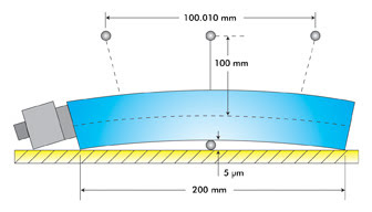
Figure 1. Depicted is a 200-mm stage on a nonflat surface. For sectors
and chords, the angle (α) can be derived with the following formula: α = 8 x h/L =
8 x 0.000005/0.2 = 200 μrad = >100 μrad for 100-mm travel.
Referring to Figure 1 again, the sample is either 100 mm above
the theoretical plane of the drive screw that may have a motor-mounted rotary encoder
or above the plane of the linear encoder. Because of the induced pitch error, the
point of interest is now ahead by 10 μm (100 μrad x 100 mm). Of course,
the closer the sample is to the measurement plane, the less pitch error effect there
is.
In this case, 5-μm flatness introduces a pitch error of 100
μm. For a less flat table, the pitch error can only become worse.
To eliminate the effect of nonflat surfaces, a number of solutions
are available, if one has a steel table. Mounting stages on granite bases with flatness
of 5 μm or less (available from Newport Corp.) and placing the granite base
on the table will reduce the effect of the lack of table flatness. Another method
is to use three-point kinematic supports under the stage, which defines a perfect
plane, thereby eliminating distortions. However, the precision stage in this condition
must be very stiff, with enough rigidity to handle the unsupported sections of the
stage.
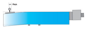
Figure 2. If a stage is not fully supported, pitch errors can occur
when a load moves toward the unsupported side of the stage.
Base support and load distribution
Another source of error is the amount of support underneath the
precision stage. Ideally, the base of the stage is fully supported, so the load
is distributed through the bearing elements into the base and evenly over the mounting
surface. In Figure 2, a 600-mm stage is supported only at the middle of travel.
As the 60-kg load is moved to the extreme ends, the load induces a pitch error.
The left graph in Figure 3 shows a pitch error of 450 μrad.
Using simple geometry with a sample at 100 mm from the measurement plane, this equates
to a 45-μm linear error at each end of travel, as shown in the right graph.
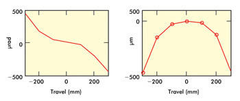
Figure 3. In this example, a 450-μrad pitch error equals a 45-μm linear error.
A specific case of load distribution is on X-Y stacks where the
load can cause angular deviations as the center of gravity moves beyond the bearing
support of the lower X-stage, in the overhang region (Figure 4). Usually for high-precision
products, stiffness constants are provided by experienced suppliers of motion products.
In this example, the angular deviation constant around the X-axis, kαx, equals 1
μrad/N-m.
When the 5-kg load is moved to the extreme position of the Y-axis,
the resulting roll angle deviation to the X-axis is 12.5 μrad. Similar to the
effect in Figure 1, this angular deviation acts as a pitch error effect on the Y-axis.
Also, this roll angle equates to a flatness of 3.13 μm. With an X-stage that
has a wider base, the angular deviation constant will be smaller, so the effect
of overhanging loads is less.
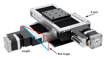
Figure 4. In this example, travel is ±250 mm, the load on the Y-stage is 5 kg, the stiffness
constant (kαx) = 1 μrad/N-m, and the roll angular deviation due to load overhang
is 12.5 μrad (1 μrad/N-m x 50 N x 0.25 m). At the extreme end of the Y-stage,
the roll is ±12.5 μrad, and the flatness is 3.13 μm (12.5 μrad x
0.25).
It is clear from our discussion that attention must be paid to
the quality of the surface to which a precision stage is mounted, preferably 5 μm
or better. Consider also fully supporting the stage and the width of the bottom
stage to reduce the angular deviation effect. All these considerations will ensure
achievement of the performance specified by the precision stage manufacturer.
Meet the authors
Thomas Bartholomäus is director of European sales at Newport
Motion; e-mail: thomas. [email protected]. Beda Espinoza is senior manager
for product marketing at Newport Motion; e-mail: [email protected].