Nicholas A. Geisse, Asylum Research
The atomic force microscope (AFM) has seen exciting and promising growth in its combination with optical microscopy. Although new optical techniques developed in the past few years have begun to push traditional limits, the lateral and axial resolutions of optical microscopes typically are limited by the optical elements in the microscope as well as by the diffraction limit of light.
One of the most powerful abilities of optical microscopy, however, is its capacity to image through the entire depth of certain samples with chemical specificity using a plethora of label-conjugated markers that allow researchers to identify specific structures or molecules over dynamic events.
Coupled with AFM’s ability to measure high-resolution topographical features, forces and moduli (elasticities) of a sample, a more complete understanding of structure-function relationships can be achieved with a combined AFM/optical system. Although the two imaging modalities have been used in combinational studies for more than a decade, significant challenges of direct correlation of the two data sets have existed primarily because of the scaling differences between them. Recent developments in software now allow for user-friendly and intuitive routines for direct overlay and comparison between the two data sets (Figure 1).
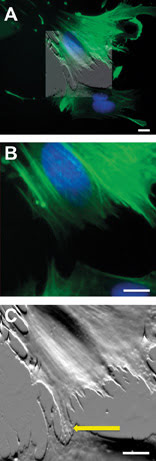
Figure 1. AFM data can be overlaid and blended (A) to desired intensity (50 percent transparency shown) onto multicolor fluorescence data to correlate structures of interest such as the fluorescently stained nucleus (blue). Detail (B) of the scanned region shows that fluorescently labeled actin filaments (green) are not detectable at the border between different cells with the optical microscope. Conversely, the AFM (C) reveals the presence of small cellular processes (arrow) connecting the two cells. Scale bars 10 μm.
Various optical techniques also are being used to modify or stimulate samples of interest in concert with AFM measurements, and vice versa. Indeed, AFM researchers find themselves in a diverse, multi-interfacial area of microscopy, made even more powerful by combining AFM with optical microscopy.
Biomaterial interfaces
Biological and bioengineered systems are particularly well suited for study with the combined imaging modalities.
Since the early 1980s, researchers have learned that the material properties of the physical interface between cells and their environment can play important roles in their structure, function and development, and that these influences are not directly genomic. This knowledge has become increasingly important as biologists, engineers and materials scientists have begun to make breakthroughs in tissue engineering – a key aspect of the emerging field of regenerative medicine.
Understanding the structure and patterning of various organelles in these designer cells and tissues is crucial in this field, and a combined AFM/optical instrument can readily show investigators both the three-dimensional topographical structure and the composition of various components within that structure. For example, an epifluorescence,1 confocal and AFM analysis2 of shape-engineered cardiac myocytes showed that the extracellular (outside) boundary conditions of the cell determine the self-assembly pattern of the intracellular cytoskeleton (Figures 2A,B). Confocal data (Figure 2C) demonstrated that cells segregate the nucleus and cytoskeleton in the vertical direction, and fluorescence data overlaid onto AFM images showed that ridges seen on the topography correspond to the contractile machinery of the myocyte (Figure 2D).
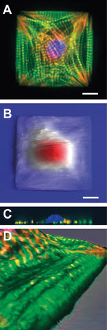
Figure 2. Engineered cardiac myocytes fluorescently labeled for actin (green) a-actinin (red) and DNA (blue) show ordered structure (A). AFM scans of live engineered cells with streaks corresponding to cell beating show a fried-egglike morphology (B) confirmed by confocal microscopy depth projections on fixed cells (C). Zoomed-in detail of 3-D-rendered fluorescence and AFM data overlay show that long ridges seen in AFM topography coincide with organized myofibrils (D). Scale bars 10 μm. Panels (B) and (C) adapted from Geisse et al, 2009.
Further, additional studies at the University of Pennsylvania in Philadelphia by Dennis E. Discher and Adam J. Engler (now at the University of California, San Diego, in La Jolla) that exploit the force-measuring ability of the AFM have shown that development of these structures also is influenced by the mechanical properties of the cell-substrate interface.3
The ability of the AFM to correlate surface topography with internal structural information from fluorescence also has been used to understand mechanisms of membrane fusion in mast cells.
Using a combination of topographical mapping and fluorescent staining, Liu and co-workers4 identified optically invisible surface membrane ridges that formed concurrently with optically visible F-actin filaments, a previously uncharacterized mechanism. It also was discovered that the secretory process in these cells is not mediated by actin filaments, suggesting that the cytoskeleton is a poor target for therapeutic strategies. This is important because mast cell degranulation is a key event in allergic and immunoprotective responses.
Expanding on the ability to correlate topography and biochemical information, a combined AFM/optical system has the added benefit of allowing the investigator to interact with a sample and to physically manipulate it. Researchers at the University of California, Berkeley, used a carbon-nanotube-modified AFM tip to penetrate the cell membrane and physically inject molecules of interest without damaging or killing the cell.
In this case, transmitted light optical microscopy guided the nanosurgical tool to the area of interest within the cell, while fluorescence microscopy confirmed the internalization, localization and lifetime of the molecules for several hours after injection into the cell.5 The work offers many new possibilities for direct genetic and proteomic manipulation of individual cells, which has been an important strategy in bioengineering but has been hampered by the relative destructiveness of traditional micron-scale injection techniques.
Design challenges and solutions
Technical challenges exist when integrating optical and atomic force microscopes. Optically interfaced AFMs require a robust, custom-made stage to support the instrument and to minimize mechanical noise (Figure 3).
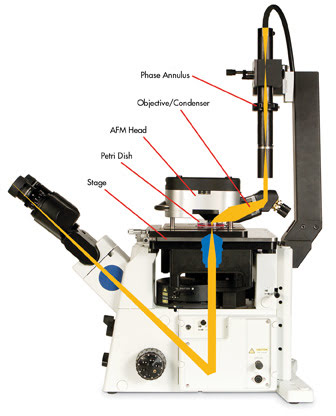
Figure 3. Inverted optical microscopes can be coupled to scanning probe microscopes without restricting optical resolution and providing top-down optical access (schematic: MFP-3-D-BIO AFM from Asylum Research integrated with an inverted optical microscope).
Typically, these stages also must be designed so as not to limit the movement or selection of optical microscope objectives or to curtail the risk of mechanical interference between the stage and the optical microscope. Further, the design of the AFM components and stage must accommodate the piezos, flexures and sensors discussed above, while minimizing the mechanical loop between the tip and the sample because the susceptibility of the AFM to noise and thermal drift increases with the size of the loop.
The AFM uses a laser or superluminescent diode (SLD) to track the position of the cantilever, so there must be several considerations in the design of the optical lever to minimize interference and crosstalk to the desired optical data. Some of the earliest commercial instruments used a red laser diode for optical lever tracking. These diodes were problematic for AFM in general because they would readily couple optical interference fringes into AFM images and force curves taken on reflective samples. The visible red diodes also would be seen in images taken on the optical microscope, concomitantly preventing the detection of fluorophores that excite or emit within the wavelength range of the diode.
Interference fringes coupled into AFM data were greatly attenuated by the introduction of low-coherence superluminescent diodes that emit infrared wavelengths. Although SLDs greatly reduce AFM data noise and reduce the amount of light emitted at visible wavelengths, their nature does result in a faint emission in visible wavelengths that can interfere with highly sensitive optical measurements.
The addition of a narrowband filter at the SLD source eliminates this interference, although many commercial AFMs omit such a filter because of the cost or difficulty of incorporation into the optical lever design. And although many scientific-grade CCD cameras used to record images with the optical microscope are sensitive to wavelengths in the IR, the addition of a well-designed filter under the microscope objective can block these signals from saturating the camera electronics.
A further design difficulty presents itself with the incorporation of top-down optical access into AFM designs. Several AFM designs do not limit optical access below the sample (resulting in the ability to place the AFM on inverted optical microscopes), but certain samples may be opaque or may require mounting on opaque sample holders that prevent the use of the inverted microscope optics.
These issues are becoming more prevalent because opaque samples such as polymers, ceramics and silicon-fabricated devices are garnering more interest across the materials, engineering and biological sciences. To achieve quantitative data collection, high linearity and low noise performance, various components of the AFM must be mounted directly above the optical lever, which limits top-down optical access. With this in mind, it would seem that AFM designs would be forced to trade off data quality with optical access.
One common solution is to incorporate a large access hole in the AFM head, directly above the optical lever. Although this design allows for optical access directly through the top of the AFM head and the use of some of the transmitted light condensers from the optical microscope manufacturers, it also compromises the mechanical design of the AFM head and the accuracy of the optical lever, preventing the collection of truly quantitative force data.
In some designs, ancillary cameras or optics must be added next to the instrument, or an entirely different base must be used for visualization and documentation of the top-down view for opaque samples. These measures complicate experimental design because of space restrictions in the necessary acoustic isolation equipment or in the difficulty in mechanical reproducibility when moving the AFM to other equipment.
Other designs maintain the various components of the AFM head directly above the tip to preserve high-quality quantitative data collection, and incorporate a series of mirrors and high-quality objective lenses to provide top-down optical access through a customized optical microscope condenser (Figure 3).
Although more costly, the added advantage of this design is that the objective lens can be used as both a condenser for transmitted light techniques, such as bright-field and optical phase contrast, and as a viewing element for optical lever alignment and region-of-interest identification on opaque samples without the use of extraneous equipment or separate bases.
Future challenges
Coupled with the innovations in optical microscopy developed across centuries, the challenge of designing AFM instrumentation that can be seamlessly integrated with advanced optical techniques while preserving quantitative data collection is paramount to the future success of the technique. Advances and innovations that make current studies possible demonstrate that we are well on our way to a bright future.
Meet the author
Dr. Nicholas A. Geisse is a staff scientist for biology at Asylum Research in Santa Barbara, Calif.; e-mail: [email protected].
References
1. M.A. Bray et al (2008). Sarcomere alignment is regulated by myocyte shape. Cell Motil Cytoskeleton, Vol. 65, p. 641.
2. N.A. Geisse et al (February 2009 online). Control of myocyte remodeling in vitro with engineered substrates. In Vitro Cell Dev Biol Anim, in press.
3. A.J. Engler et al (2004). Myotubes differentiate optimally on substrates with tissue-like stiffness: pathological implications for soft or stiff microenvironments. J Cell Biol, Vol. 166, p. 877.
4. Z. Deng et al (2009). Impact of actin rearrangement and degranulation on the membrane structure of primary mast cells: a combined atomic force and laser scanning confocal microscopy investigation. Biophys J 96, p. 1629.
5. X. Chen et al (2007). A cell nanoinjector based on carbon nanotubes, PNAS, Vol. 104, p. 8218.