Adaptive optics helps improve ophthalmic and microscopy applications.
Paul Bierden and Steven Menn, Boston Micromachines Corp.
Biological imaging instruments often have resolution limitations
that restrict the ability of researchers and clinicians to detect critical detail.
One reason is that, as light passes through tissue to reach the object of interest
— a cell, the retina or a tumor — the tissue induces wavefront aberrations
in the light.
Adaptive optics can actively correct these aberrations
in the optical path between the camera and the object being imaged. The increased
resolution allows vital information to be extracted from biological specimens. Introduced
in the 1950s as a way to correct for air-induced turbulence in ground-based astronomy,
adaptive optics has seen a dramatic increase in use over the past 10 years across
many fields, including bioimaging.
The technique is being tested in various
biological applications and could be useful for even more. For example, retinal
imaging is currently limited in resolution and contrast by the imperfections in
the cornea and crystalline lens, as well as by the viscous and nonuniform nature
of the vitreous humor in the eye. Thus, clinicians are unable to view the important
cellular structures.
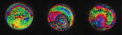
Figure 1. These aberrations introduced by biological specimens were
measured by phase-stepping interferometry. The phase of the wavefront is encoded
as a hue scale, and brightness represents the wavefront amplitude. The specimens
are rat brain tissue (left), mouse oocyte (center) and mouse liver tissue (right).
Courtesy of Martin J. Booth, Oxford University.
In vivo cellular-level imaging would
enable early and accurate diagnosis of diseases of the eye. And, in general
biological microscopy, aberrations induced by imaging through thick tissue produce
optical distortion that results in reduced signal levels and degraded resolution
(Figure 1), but adaptive optics can provide a means to create high-resolution images
through a thick medium.
All adaptive optics systems are composed
of a wavefront sensor that measures the phase aberration in the optical wavefront,
a deformable mirror that adjusts its position to correct for the aberration, and
a control system that takes measurements from the sensor and calculates the required
movement of the deformable mirror (Figure 2).
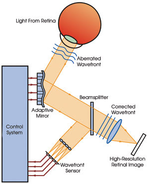
Figure 2. Adaptive optics systems contain
a wavefront sensor, a wavefront corrector and a controller. Courtesy of David
R. Williams, University of Rochester.
The most prevalent wavefront sensor
with adaptive optics in biological imaging systems is the Shack-Hartmann model,
which breaks the incoming wavefront into a number of small pieces using an array
of miniature lenses called lenslets. The light from each lenslet is focused onto
a CCD camera. As the portion of the wavefront hitting the lenslet is aberrated,
the focused spot on the CCD camera moves. The amount of aberration in that area
of the wavefront can be calculated with simple geometry that uses the focal length
of the lenslet and the translation of the focused spot (Figure 3).
Other techniques for wavefront sensing,
such as curvature sensors, pyramid sensors and “model free” hill climbing,
also are used in bioimaging.
The deformable mirror is the adaptive
element of the adaptive optics system (Figure 4). Based on information provided
by the controller, it changes its shape to correct for the aberration in the wavefront,
thus cleaning up the image. It is essentially a thin, flexible mirror with control
points behind it that adjust shape and position.
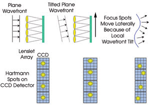
Figure 3. The Shack-Hartmann wavefront sensor is commonly used in adaptive optics systems. Courtesy
of B.M. Levine, NASA/Jet Propulsion Laboratory.
There are several methods for adjusting
the mirror’s shape. Macroscale mirrors — those with apertures between
70 and 150 mm — use piezoelectric stacks to deform the surface, while deformable
mirrors based on microelectromechanical systems (MEMS) use electrostatic actuators
to control movement. In membrane-based types, a localized electrostatic field acts
directly on the mirror.
The number of control points, or actuators,
ranges from 19 for a simple membrane mirror to more than 4000. The number of control
elements required is determined by the aperture size of the imaging system and the
complexity of the aberration for correction. In most biological imaging applications,
100 to 200 points are sufficient.
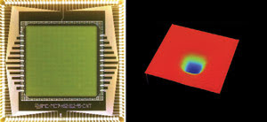
Figure 4. This 140-element
Boston Micromachines MEMS-based deformable mirror has a 4.4-mm aperture (left).
A surface map of the mirror with 3.8 μm of deflection was measured by a Veeco
white-light surface-mapping interferometer (right).
For many years, the only deformable
mirrors available were large-aperture types that were designed and built for defense
and astronomy applications. Although they were sufficient for these purposes, they
had limitations when applied to biological imaging. Their large sizes — on
the order of 100 mm in diameter — complicated the optical system intended
for imaging a field of view only 5 mm in diameter. Additionally, their cost was
prohibitive for a commercial imaging system. Despite these limitations, most early
work in adaptive biological imaging was done with a large mirror.1,2
In the past five to 10 years, there
has been a great deal of effort to reduce the size and cost of the deformable mirror.
The ability to use semiconductor fabrication techniques, which lend themselves to
small sizes and low costs with the economies of scale, makes MEMS the most promising
technology. Matching the performance of their large-scale counterparts,3 MEMS mirrors
have met the pricing and size needs of biological imaging systems and are being
implemented around the world.4,5,6
The controller that brings together
the sensor and deformable mirror is simple. It uses signals from the wavefront sensor
to calculate the error from the desired wavefront (usually planar) and sends a signal
to each of the actuators in the deformable mirror to compensate for that error.
The calculation must be performed repeatedly and faster than the changing wavefront.
A standard computer can control the adaptive optics system because of the low actuator
count (100 s) and speed requirements (100 Hz) for biological imaging applications
(as compared with atmospheric correction where 1000 channels and 1 kHz are required).
These components have been integrated
into a number of imaging instruments, including scanning laser ophthalmoscopes,
confocal microscopes, two-photon microscopes, optical coherence tomography (OCT)
systems and scanning optical microscopes.
Retinal imaging
According to the National Eye Institute, more
than 3 million Americans are blind or visually impaired — many suffering from
one of the three most common retinal diseases: glaucoma, macular degeneration and
diabetic retinopathy. With growing rates of diabetes and an aging population, vision
scientists are actively pursuing techniques such as scanning laser ophthalmoscopy
and OCT to improve retinal imaging and to advance the understanding, diagnosis and
curability of eye pathologies.
Adaptive optics has enabled high-resolution
imaging in both retinal imaging and biological microscopy. A long-standing goal
in vision science had been cellular-level imaging of a living human retina. In 1999,
researchers led by Austin Roorda and David R. Williams demonstrated high-resolution
adaptive optics scanning laser ophthalmoscope images of the retina that resolved
individual photoreceptors.7
According to Williams, adaptive optics
has provided a two- to threefold improvement in resolution for retinal imaging.
This could be especially useful because a standard perimetry test administered by
an optometrist won’t detect a disease until it affects the patient’s
vision. However, examination of the eye’s receptors with an adaptive optics
imaging system could reveal such a disease. If integrated into clinical instruments,
the systems could enable earlier diagnosis, improved monitoring of therapy and a
better understanding of pathogenesis.
Dr. Stephen A. Burns, a professor of
optometry at Indiana University in Bloomington, uses an adaptive optics scanning
laser ophthalmoscope to compare photoreceptor health to changes in retinal scattering
and polarization properties (Figure 5). The enhanced resolution has enabled high-speed
imaging to see blood cells moving in capillaries. This sort of vital detail could
aid in the early detection of diabetic retinopathy.
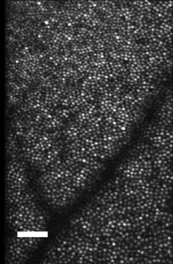
Figure 5. The image of the cones near the fovea shows increases in cone size as one
goes from the fovea to the more peripheral retina. Courtesy of Dr. Stephen A. Burns.
Scale bar: 50 μm.
Adaptive optics also can help shorten
imaging time in ophthalmic imaging. There are safety restrictions concerning the
intensity of light that can be put in the eye, and compensating for this requires
imaging over a longer time period. Poor optical efficiency caused by aberrations
means that many of those photons are lost, but the optics can help more of that
light make it back to the detector, speeding the imaging time.
A similar issue exists in microscopy.
Low optical efficiencies demand an increase in illumination power required for imaging,
but this high power gradually kills or harms the specimen. An increase in optical
efficiency permits the use of lower illumination powers, extending the time
over which specimens can be imaged.
Martin J. Booth of the department of
engineering science at Oxford University in the UK is interested in the application
of adaptive optics to high-resolution three-dimensional optical microscopy for biological
imaging. He is particularly interested in aberration correction for confocal and
multiphoton fluorescence microscopy (Figure 6). Booth has shown that adaptive optics
restores fluorescence signal levels at up to a tenfold increase,8 permitting the
use of lower illumination power and increasing specimen viability. It can clearly
be seen that it increases the brightness of the fluorescence.
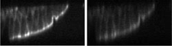
Figure 6. These confocal fluorescence microscope
images of a fluorescently stained mouse kidney section show what occurs with (left)
and without (right) aberration correction. The optic axis is vertical. Courtesy
of Martin J. Booth, Oxford University.
Adaptive correction of aberrations
also can enable imaging deep into specimens, i.e., imaging of living tissue, while
maintaining high resolution and signal levels. Booth noted that high-resolution
optical microscopy is limited to thin specimen sections or individual cells on microscope
slides. “In many cases, it is biologically much more interesting to look at
cells and cellular processes in their natural environment — within living
tissue,” he said.
At the Center for Automation Technology
at Rensselaer Polytechnic Institute in Troy, N.Y., researchers led by Benjamin
Potsaid have addressed the inherent trade-off between resolution and field of view
in microscopes that use adaptive optics. The microscope design, called the adaptive
scanning optical microscope, optically scans over a large field of view, imaging
features as small as 1.5 μm over areas as large as 40 mm.9 However, aberrations
introduced by passing the light off-axis through the optical path cause blurring
toward the edge of the image. By using adaptive optics, a deformable mirror
can correct for the position-dependent aberrations to achieve diffraction-limited
image quality over the entire observable field.
The microscope allows the researchers
to observe the effect of potential therapeutic chemicals on the mitotic (cell division)
process over a large population of living cells in real time (Figure 7).
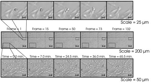
Figure 7. In an image
of cell mitosis, a single cell can be observed with high resolution and a large
field of view. The resolution is not distorted at the edges because of adaptive
optics.
Although the field of adaptive optics
has had more than 50 years to mature, its application to bioimaging is still relatively
new. As with any developing biomedical technology, challenges exist in the transition
from research to clinical commercialization.
Wavefront sensors, originally designed
for astronomy and free-space communications, are not always well-suited for microscopy
and vision science, so researchers have had to develop new methods of wavefront
sensing. Given the complexity of these sensing systems, it may even be easier to
eliminate the sensor altogether, creating a “wavefront sensorless adaptive
optics” method.10 Based on the principle that maximum light is measured when
the wavefront is optimized, a deformable mirror controls the wavefront through sequential
application of various aberrations.
Although there have been many breakthroughs
in deformable mirror performance in recent years, applications continue to push
development. Burns pointed out that aging eyes have more aberration at high spatial
frequencies. This requires more stroke at higher-order corrections, which have proved
fundamentally difficult for membrane deformable mirrors.
A number of groups are working to increase
the stroke of their mirrors to meet the needs of the general population. For example,
later this year, Boston Micromachines Corp. will release a high-stroke deformable
mirror system that performs 12 μm of wavefront correction. An additional configuration
implementing a novel optical design will increase this to 24 μm, which
will enable retinal imaging in more than 95 percent of the population.
Meet the authors
Paul Bierden is president and CEO of Boston Micromachines Corp. in Watertown, Mass.; e-mail: [email protected].
Steven Menn is director of product marketing at the company; e-mail: [email protected].
References
1. A. Roorda and D.R. Williams (2000). Adaptive optics and retinal imaging. OSA TRENDS IN OPTICS AND PHOTONICS, Vol. 35, pp. 151-162.
2. D. Miller et al (2003). Coherence gating and adaptive optics in the eye. Proc SPIE, Vol. 4956.
3. N. Doble et al (Sept. 1, 2002). Use of a microelectromechanical mirror for adaptive optics in the human eye. OPTICS LETTERS, pp. 1537-1539.
4. Y. Zhang et al (2006). Adaptive optics scanning laser ophthalmoscope using a microelectromechanical (MEMS) deformable mirror. Proc SPIE, Vol. 6138.
5. Gleb Vdovin et al (June 2005). Subjective adaptive correction of the aberrations of the human eye. Proc SPIE, Vol. 5823.
6. E. Daly et al (January 2006). Requirements for MEMS mirrors for adaptive optics in the eye. Proc SPIE, Vol. 6113.
7. A. Roorda and D.R. Williams (Feb. 11, 1999). The arrangement of the three cone classes in the living human eye. NATURE, pp. 520-522.
8. M. Schwertner et al (December 2004). Characterizing specimen-induced aberrations for high-NA adaptive optical microscopy. OPTICS EXPRESS, pp. 6540-6552.
9. B. Potsaid et al (Aug. 22, 2005). Adaptive scanning optical microscope (ASOM): A multidisciplinary optical microscope design for large-field-of-view and high-resolution imaging. OPTICS EXPRESS.
10. M.J. Booth (Feb. 20, 2006). Wave-front sensor-less adaptive optics: a model-based approach using sphere packings. OPTICS EXPRESS, pp. 1339-1352.