Hardware-based drift compensation is helping to maintain microscope focus over long periods of time.
Hank Hogan, Contributing Editor
For Alexey Khodjakov, a researcher at the New York State Department
of Health’s Wadsworth Center in Albany, it wasn’t a question of if but
when he would lose focus. Following cells as each divided into many, he and colleagues
in his lab conducted experiments for 72 or 96 hours, zeroing in with a research
microscope on mammalian cells that were typically 5 to 10 μm thick. The depth
of focus depended on the optics, but it was usually less than 1 μm. When the
air conditioning cycled on, the focus would move up or down by a micron or two —
enough to cause problems.
Traditional focus-maintaining solutions didn’t
work, so Khodjakov turned to a relatively new technology, hardware-based drift compensation.
Microscopes using the technique solved his problem and allowed him to collect data
for 96 hours or longer.
Khodjakov used a Nikon system, but
systems also are available from Olympus America Inc. of Melville, N.Y., and Applied
Scientific Instrumentation (ASI) Inc. of Eugene, Ore. Although there are differences
in implementation, these systems work in a similar fashion. They send red light
through the optics, reflect it off the coverslip in various ways, capture the reflection
of light and use that information to find the coverslip. They then maintain a constant
distance to that reference point to within a fraction of a depth of field.
The limits of stability
Microscope focus can drift because of temperature
changes and the pull of gravity on an objective-laden — and, therefore, heavy
— turret. In the past, the problem was solved in a number of ways. One was
by throwing people at it; for example, by assigning students to maintain focus.
That method is expensive and doesn’t work well.
A more sophisticated approach involves
software-controlled autofocus; the best focus is found by maximizing the contrast
for an object in the field. The up to six seconds that this method requires is too
slow for some applications. In addition, the technique exposes the sample to light,
which can be a problem for living cells. In some cases, contrast-based autofocus
can rob researchers of data by diverting some of the maximum allowable light from
imaging to focusing. “If you only have 200 exposures before your cell dies,
you want to record all 200,” Khodjakov said.
A final solution employs environmental
chambers that keep the setup at a constant temperature. These are typically used
to maintain cells at a desired temperature, but they also control thermal drift.
Unfortunately, the chambers are expensive, take up room and don’t work in
all situations.
Over the past five to 10 years, microscopes
have become much more stable. Stan Schwartz, vice president of product and marketing
at Nikon Instruments in Melville, N.Y., noted that, beginning about 1998, his company
embarked on a concerted effort to reduce focus drift to a minimum. Mechanics were
improved, problems with heavy objectives solved and special alloys resistant to
thermal change employed. Those enhancements were combined with linear encoders,
motorized assemblies that can move a stage or objective to a precise location. The
focusing mechanism, for example, now has a stepping accuracy of 0.05 μm.
Such efforts by microscope vendors
mean that today’s systems stay in focus plus or minus a micron or two. Going
beyond that level, however, proved to be difficult with passive techniques, Schwartz
said. “What we found out was that there was still thermal drift. There is
thermal drift in the stage plate and other mechanical components, as well as thermal
expansion and contraction in the specimen chamber itself,” he said.
Continuous correction
Several types of studies are affected by the
inability to hold or to quickly come into focus. For example, constant focus is
important in long observation studies of living cells such as the type of investigations
done by Khodjakov and in total internal reflection fluorescence (TIRF) microscopy.
The TIRF technique produces an excitation height of 0.1 μm, so keeping the
focus to within 1 μm isn’t good enough.
Nikon’s Perfect Focus System
uses a patented offset lens implementation, and a small laser diode at 770 nm gets
the reflection off the coverslip. It was introduced on the company’s PE-2000
E2 microscope.
For correcting focus, the optics must
be on the coverslip, but researchers typically want to look at some other point.
By using an offset lens, they can do this while the system continues to correct
for focal drift every few hundred milliseconds.
The autocompensation system adds about
$20,000 to the price of the microscope, according to Stephen Ross, a senior scientist
at Nikon Instruments and manager of product and technology. Adding drift compensation
raises the price, but for a type of microscope that costs more than $100,000, the
extra expense isn’t extreme, he added.
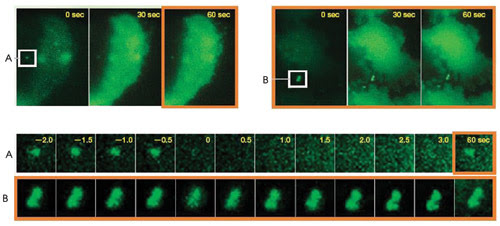
These shots of rapid calcium imaging show how a drift-compensation
system — in this case, from Nikon — can correct for thermal changes.
Two particles adhered to the coverslip are tracked from 2 s before to 60 s after
the addition of the reagent. (A) did not have drift compensation, while (B) did.
As a result, (B) stays in focus while (A) goes out until the drift-compensation
system is turned on 60 s after the reagent is added.
Retrofitting to perfection
ASI also has a hardware drift-compensation product,
which it introduced in response to requests from researchers. Because the company
doesn’t make its own microscopes, its solution, dubbed Continuous Reflective-Interface
Feedback Focus (CRIFF), is designed to work with any system using an objective lens
with a numerical aperture of at least 1.4 and a photo port. “Because we use
a 780-nm laser diode, whatever filter sets are used inside the microscope have to
have a notch or be able to pass that,” added John Zemek, executive director
of ASI.
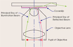
The ASI drift-compensating
unit works by total internal reflection off the coverslip, recording the position
of the reflected beam after the system is locked down. It then maintains that position
and the spacing to the coverslip. It requires an objective with a 1.4 or higher
numerical aperture.
This wavelength was selected because
it is biologically safe. It does interfere with the use of far-red fluorescent
labels, however. As a partial solution, the beam, which uses only 1 mW of power,
can be switched off if need be to take a measurement.
Alignment tweaked
The laser provides visible light that can be used
during setup to get everything properly aligned. The company does a prealignment,
but because the product is an add-on, end users must perform a final tweak. According
to Zemek, this takes less than half a minute and doesn’t need to be redone
unless an objective is changed or something else in the optical path is altered.
The company’s approach uses total
internal reflection off the coverslip. The location of the returning beam on the
position-sensitive photodiode is recorded as a reference so that users can focus
on an object while deviations from the reference are measured. The unit costs about
$9000 and works in combination with one of ASI’s Z-axis drives or piezoelectric
stages.
Simon C. Watkins, a professor of cell
biology, physiology and immunology at the University of Pittsburgh, uses the ASI
system to study cell surfaces, thin structures 100 or 200 nm thick. With his setup,
that thickness equals a single focal plane, so any drift could render data meaningless.
Before using the system, he employed a combination of manual adjustments and automated
movements to previously registered positions. With automated drift compensation,
he has run experiments over several days and also has set up the system, gone away
for a week to a conference and returned to find it still in focus.
However, he added, it is not time alone
that is important. An experiment that collects 100 fps of data may run only a few
minutes. During that span, the focus can’t drift. “It’s not the
time. It’s the consistency that’s important,” Watkins said.
At the University of California, San
Diego, neuroscience microscopy shared facility, managing director Brendan C. Brinkman
noted that most research at the facility involves incubating live cells. Investigations
on fast calcium dynamics, for example, may run a few tens of minutes at most. In
that time, a great deal of data can be collected. Other studies, though, run for
24 to 48 hours, as time-lapse images of growing cells are captured. Despite the
different timescales, both sets of experiments have similar requirements.
“You need to make sure that your
images are going to be stable in between time points or that your system is going
to be stable in between time points,” said Brinkman. “If it’s
not, you’re going to have trouble doing things like particle tracking or collocalization
of various fluorescent signals.”
He recently purchased the Zero Drift
system, an automated drift compensation-equipped microscope from Olympus. He plans
to use it, along with a temperature-controlled chamber, to ensure image stability.
The system joins the facility’s other Olympus microscopes.
That company’s approach identifies
the position of the coverslip using the reflection of a 785-nm laser and then, via
software, offsets to a user-defined distance in the Z-axis relative to that point.
After that, it checks its location as needed and corrects for drift.
Zero in on focal point
According to Edward A. Lachica, group manager
of imaging systems at Olympus America, the system works because its inherent stability
is great enough to prevent too much drift between focal checks, which are done before
capturing an image. What is more, he said that correcting too often can lead to
jitter because the correction may take place during the snapping of an image.
Besides minimizing the effect of temperature
changes or the pull of gravity, Lachica pointed out that drift-compensation systems
offer another benefit: They can overcome physical imperfections. Microtiter plates,
for example, may have an effective change in focal point of 25 or 50 μm from
one side of the plate to the other. In the past, in evaluating a 96-well plate,
an investigator might have employed a software-based algorithm that would take 0.1
minute per well to find the focal point.
With a hardware-based system, that
time can be slashed significantly. The Olympus system finds the coverslip in 800
ms, a greater than 5 s savings per well. Because of that time savings, Lachica foresees
drift-compensation systems being widely used in pharmaceutical research and other
high-content applications. “It will significantly reduce the amount of time
needed by an investigator to go through a titer plate,” he said.
The system costs approximately $25,000
and consists of a completely motorized microscope, without cameras or other components.
These solutions aren’t perfect.
For one thing, they’re expensive and may require purchasing an entirely new
microscope. For another, their use limits some of the dyes that researchers can
employ. Even with these drawbacks, Khodjakov’s experience has led him to make
a prediction about the technology: “This is going to be really big. It’s
a universal improvement for many people.”
In an ideal world, microscopes would
be locked away in temperature-controlled chambers, protected by enclosures from
environmental disturbances. In the real world, that is often not practical or economical,
but drift-compensation technology could allow microscopes to be used in a more typical
environment.
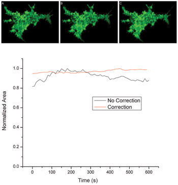
These images and the accompanying data show that Z-drift correction improves TIRF image
stability over longtime course imaging. The images show HEK-203 cell membranes adjacent
to the coverslip. Without Z-drift compensation, there is significant variation of
about 20 percent in area (see graph) versus about 4 percent if correction is done.
The researchers took image A at the start of the run, B at 5 minutes and C at 10
minutes. Such images are used to measure the total area over time and to quantify
the variation. Images taken by Cameron Cooper of the Stowers Institute.
Joel W. Schwartz, managing director
of imaging at Stowers Institute for Medical Research in Kansas City, Mo., has used
drift compensation for demanding TIRF imaging at fluctuating room temperature. He
said Z-drift compensators will be particularly useful because they allow the
microscope to be used in a more heavily trafficked area, such as a typical lab bench.