Pierantonio Boriero, Matrox Imaging
There is a rapidly growing interest in using 3-D machine vision to address automation requirements, including new types of inspections. Many wildly differing techniques exist to obtain a 3-D scan of a scene or object for subsequent analysis. The prevailing technique for industrial applications involves imaging a beam projected onto an object as the object moves across the beam, or vice versa.
Various vendors offer devices that integrate a laser and image sensor to simplify startup – but this simplicity comes at the expense of flexibility. For those who want to retain flexibility, the following factors must be taken into account when putting together a 3-D scanning system based on discrete components: component selection, component mounting and its effect on measurement resolution and range, system calibration, beam extraction and basic 3-D analysis. Multiple such systems also can be used jointly to deal with occlusions, increase measurement density and reduce displacement requirements.
Generating the beam
At the core of 3-D profiling is the projection of a sheet of light, which is seen as a beam as it intersects the object to scan. The points to consider when choosing this light source are its power, fan angle or field of view, working distance, thickness and wavelength. The power determines the ability to produce a bright-enough beam given the object to scan and the ambient lighting conditions. The field of view is about a slice rather than a volume, and is dependent on the relative position of light source and camera (Figure 1) as well as the optics associated with the light source. The working distance is the optimal operating range of the light source, which also depends on the lens used to focus the beam. A longer working distance results in a wider, thicker, less-intense beam. A thinner beam helps with the accuracy of extracting the beam from the image. The choice of wavelength emanating from the light source is a function of the camera’s sensor response (typically best at near-IR), the wavelength and amount of ambient light, and the color of the object. The wavelength of light typically used is thus in the near-IR range.
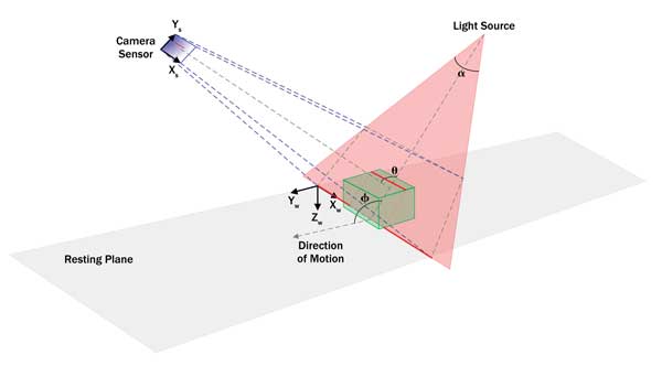
Figure 1. The geometry of a 3-D profiling system.
The beam produced specifically by a laser is subject to a phenomenon called speckle, which is static noise introduced essentially as the laser light interferes with itself while interacting with the object’s surface structure. Speckle adversely affects the process of accurately locating the beam in the image. One method to mitigate the phenomenon is to scan while the object is moving to blur the image of the beam. This can, however, be difficult to achieve at higher scan rates. A similar solution is to bring the camera’s lens slightly out of focus to again blur the image of the beam. Another way to eliminate the phenomenon is to apply a median software filter to the image of the beam along the direction of the latter. Yet another way to counteract this phenomenon is by putting an active diffuser in front of the laser to randomize the noise.
The issue of speckle can be avoided altogether by using a noncoherent light source (i.e., an LED- or DLP-based projector) to produce the sheet of light, but then an optical filter or enclosure to shield the system from the effects of ambient light becomes more critical. In any case, an optical filter or enclosure is strongly recommended when scanning reflective parts because ambient light reflections can confuse the beam extraction process.
Imaging the beam
Just as with the light source, the camera and its associated lens will similarly affect the field of view, which is now about volume, and the working distance. The camera sensor’s dynamic range, dependent on its full-well capacity, determines the ability to image a very low to very high contrasted beam that can occur during the same scanning sequence, given the object to scan. Using a camera with a high-dynamic-range sensor may thus be critical; using a camera whose sensor has a logarithmic response might be even more so. These characteristics are important for dealing with situations where there can be a high degree of varying contrast within the object (i.e., matte black versus reflective white surface zones). They are less critical for objects with soft matte surfaces (e.g., a chicken breast).
Mounting the components
3-D profiling is based on the principle of triangulation; the 3-D position or distance of a particular point on the object’s surface is derived from the angles of the light source and camera to this point and the fixed distance between the light source and the camera. The typical sole hard-mounting constraint for the light source is that the sheet of light it produces must be orthogonal to the scanning direction. About 50 percent of the system’s height resolution is achieved at an angle of 30º between the light source and the camera (Figure 2). Going beyond this angle significantly increases the effect of occlusion while marginally increasing the height resolution. The maximum height resolution and susceptibility to occlusion is achieved at an angle of 90º, which is suitable for just inspecting an essentially planar surface. Increasing this angle increases the height resolution, but also proportionally reduces the height range.
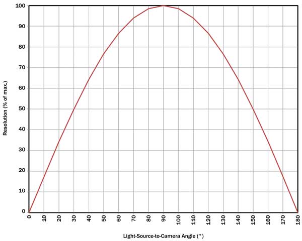
Figure 2. The effect of the light source to camera angle (θ) on resolution.
The system’s resolution is heterogeneous. That is, it is different along each principal axis. The system’s X resolution is mainly dependent upon the camera sensor’s X resolution. Its height, or Z resolution, is dependent upon the sensor’s Y resolution; the angle between the light source and the camera; and the angle between the latter two and the plane on which the object is resting (e.g., a conveyor). The Y resolution, or the resolution along the scanning direction (i.e., perpendicular to the scan slices), is dependent upon the motion speed, encoder resolution and the camera’s maximum frame rate.
The higher the camera’s frame rate, the lower the amount of light captured by the camera’s sensor, which, in turn, necessitates a brighter light source. One typically goes after the highest frame rate to maximize the slice density. A higher frame rate implies a shorter exposure time, which reduces the beam contrast, but this can be compensated for by using a brighter light source. Increasing the lens aperture reduces the depth-of-field or in-focus range, but this is usually not a major concern. Users must be mindful that increasing the frame rate reduces the effect of motion blur, which is undesirable if the latter is the method chosen to deal with laser speckle.
Reducing a camera sensor’s vertical region of interest is often an acceptable means of achieving a higher frame rate because an object’s height variation is often much less than its width and length variation (e.g., when performing surface inspection). A positional encoder is most often used to trigger image capture, but a reading also could be obtained from it once an image is captured.
An alternative to relying on a positional encoder is to use a motorized stage controlled by a stepper motor. Achieving the desired system resolution is often done through trial and error. There are many interrelated parameters to set that affect the system’s measurement resolution and range. Some vision vendors provide a calculator to help establish the required camera, lens and geometric relationships to achieve the required measurement resolution and range.
Calibrating the system
System calibration is essential for compensating for component deficiencies (from the theoretical ideal), addressing the fact that the response to variations in object height is nonlinear, and producing measurements using a real-world unit and coordinate system.
The first objective in calibration is to correct any possible optical distortions produced by the camera’s lens and the misalignment of the camera’s sensor. The second objective is to learn the relationship between the light source and the camera. Note that these first two objectives are automatically taken care of when using a precalibrated device that integrates a laser and camera. The third objective of calibration is to find out the direction and speed of the scanning motion. This is optional and depends on how well the light source and camera are mechanically aligned with the plane on which the object is moving (e.g., conveyor). The final objective of calibration is to find out the relationship between the light source and camera, and the plane on which the object is resting. The latter also is optional and often circumvented by imposing a mounting constraint: The laser must be strictly perpendicular to the plane on which the object is resting. It is always helpful to rely on a vision tool kit that offers a comprehensive solution for system calibration.
Extracting the beam
Beam extraction is a matter of detecting the beam, locating it with a high degree of accuracy, and being able to deal with varying widths and intensities. Surface reflectance has a considerable impact on the latter – as does the object’s 3-D geometry, but to a lesser extent. Both can vary significantly during the same scan.
The extraction method is a trade-off between robustness and speed. The most common methods just extract one light peak per camera sensor column. This is sometimes insufficient; the reflection of the beam off one part of the object to another can introduce a spurious light peak; the light source or camera perspective also can result in two or more light peaks-per-camera-sensor column (Figure 3). However, how to interpret and handle multiple light peaks is application-specific.

Figure 3. Perspective introduces an additional light peak.
Note that some cameras and frame grabbers can perform the beam extraction (as opposed to relying on software running on a computer). This reduces the bandwidth required to the computer’s memory and can thus increase the maximum achievable profile rate.
Analyzing the 3-D data
3-D profiling produces a point cloud, which is a collection of sampled points in 3-D space. This point cloud can be converted into a depth map, which is a 2-D image where the intensity information is replaced by height. This conversion is achieved by projecting the point cloud onto a virtual plane divided into a grid, which becomes the depth map.
There are many aspects to take into account for this projection: the grid density, what to do when multiple points project onto the same grid cell (i.e., take the minimum, maximum or average height) and what to do when there is no point to project onto a given grid cell. The latter can be addressed by assigning a specific constant value. It can also be handled by assigning the value from a neighboring cell or interpolating a value based on neighboring cells depending on whether the gap is to be treated as a discontinuity or a smooth transition. The point cloud also can be rectified so that the projection is perpendicular to a desired reference plane.
The resulting depth map can then be processed and analyzed using classical 2-D vision tools. The depth map can be subjected to a height threshold to then count the number of objects or features using blob analysis. Pattern recognition can be performed on the depth map; the advantage is that it will not be susceptible to variations in scene illumination or the object’s surface texture. Optical character recognition can be performed in situations where the character string to read protrudes from the underlying surface but has the same color as this surface (e.g., tire codes required by the US Department of Transportation). The depth map also can be used to calculate object volume; determine the 3-D orientation of the object using its principal plane; and find out the maximum, minimum or average deviation of an area from a reference plane.
Multiple light sources, cameras
Occlusion can be a critical issue when developing a 3-D profiling system (Figure 4). Occlusion results from the light source not being able to reach a certain part of the object or the camera not being able to see a certain part of the object where the beam appears. Two or more light sources can be used to overcome occlusion issues. Care must be taken, however, to ensure that the beams do not cross each other because this would cause an indeterminate situation. This can be addressed by making the sheets of light intersect each other just above the maximum expected object height and thus confine the beams to specific zones in the image. But doing this will further restrict the measurement accuracy and range.
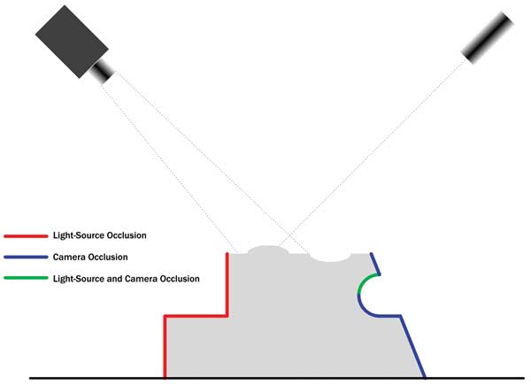
Figure 4. The occlusion of the light source and/or camera. Note that the light-source-to-camera angle is pronounced to emphasize the occlusion effect.
Similarly, two or more cameras also can be employed to deal with occlusion. There is no concern here with beam crossing, and the camera’s full vertical resolution is available to measure height. Whether to use multiple light sources, cameras or a combination of both to deal with occlusion is application-specific.
Besides dealing with occlusion, using multiple light sources or cameras will increase the density of the resulting point cloud. The need for motion to scan the object can be reduced and even eliminated by projecting multiple sheets of light from multiple light sources or a single structured light source – as long as the beams do not cross each other. The resulting measurements are sparser, but this is acceptable in applications including gap and flush control during car body assembly. Two light-source and camera pairs also can be used to measure the full volume of an object by simultaneously scanning the object from above and below (e.g., pipe, sausage or ore).
Calibrating each light source and camera combination as separate systems will increase the overall error over time, as the errors inherent in each individual system will tend to drift apart and accumulate. It is therefore important to use a vision tool kit from a vendor that enables the calibration of the individual systems as a whole.
Meet the author
Pierantonio Boriero is product line manager at Matrox Imaging in Montreal; email: [email protected].