By dividing a display screen into different subpanels and optically mapping them to various depths, a multiplane, volumetric image with correct focus cues is created.
LIANG GAO, UNIVERSITY OF ILLINOIS AT URBANA-CHAMPAIGN
The global market for virtual reality (VR), augmented reality (AR), and mixed reality (MR) continues to expand, with a variety of these technologies sprouting in the past five years, cultivated by both tech giants such as Microsoft and Google and startup companies such as Magic Leap and Meta. Despite impressive functionality, very few of these devices are crafted to meet the “human-centric design” principle1, which puts wearability and human perception at the center of hardware design and serves as the blueprint for the wearable near-eye displays’ future.
To achieve this gold standard, a wearable near-eye display must coherently integrate displays, sensors, and processors, while allowing for human-computer interaction in a compact enclosure. Among these four pillar requirements, the display plays a central role in creating a 3D perception that mimics real-world objects.
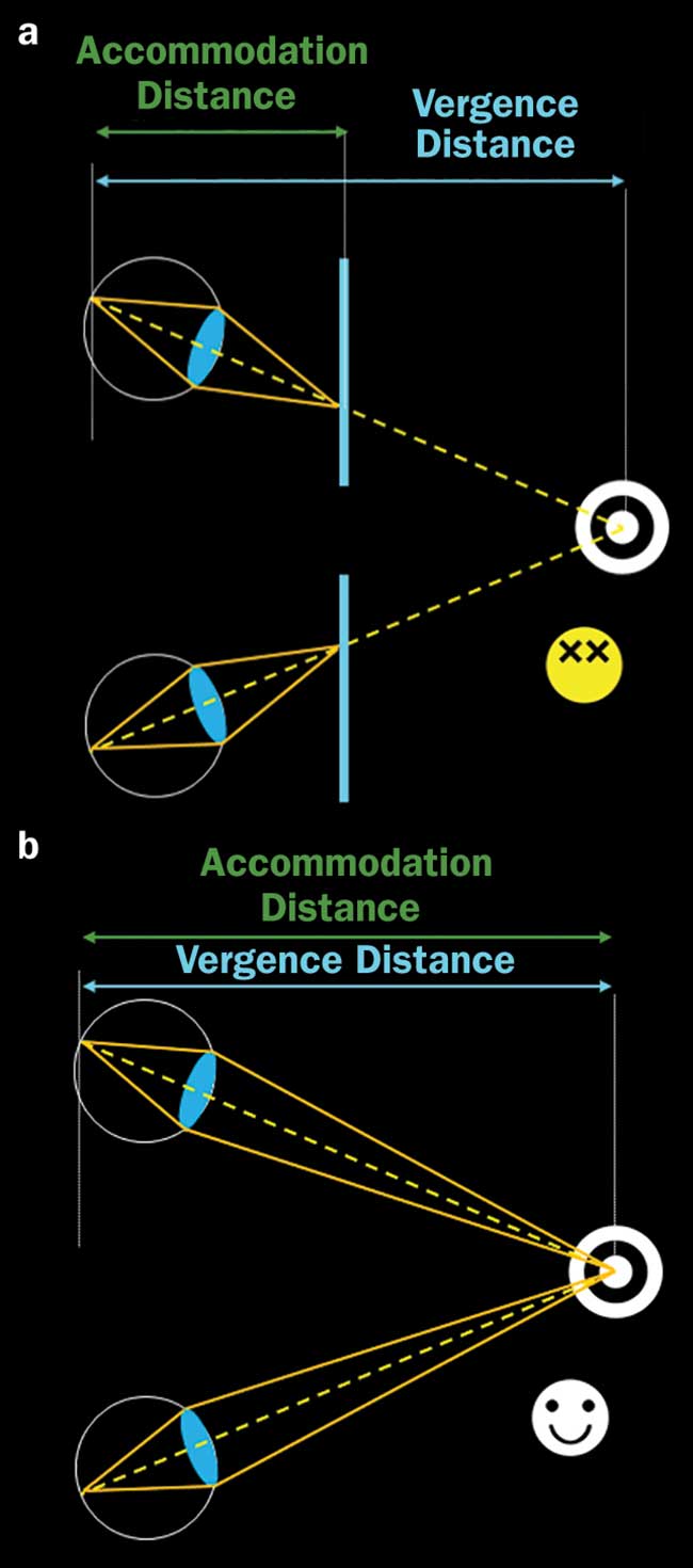
Figure 1. The vergence-accommodation conflict. Human perception of a 3D scene portrayed by stereoscopic displays. The vergence distance and accommodation distance mismatch (a). Human perception of a natural 3D scene. The vergence distance and accommodation distance are always the same (b). Courtesy of Wei Cui.
Conventional near-eye displays are based on computer stereoscopy (also referred to as 3D display 1.0), which presents two images with parallax in front of the viewer’s eyes. Stimulated by binocular disparity cues, the viewer’s brain then creates an impression of the 3D structure of the portrayed scene. However, the stereoscopic displays suffer from a major drawback — the vergence-accommodation conflict — which reduces the viewer’s ability to fuse the binocular stimuli and causes discomfort and fatigue. Because the images are displayed on one surface, the focus cues specify the depth of the display screen (e.g., accommodation distance) rather than the depths of the depicted scenes (vergence distance, Figure 1a). This is opposite to the viewer’s perception in the real world, where these two distances are always the same (Figure 1b). To alleviate this problem, the display must present a 3D image with correct focus cues that are consistent with binocular stereopsis. Such an enabling technology defines a new era (2.0) in near-eye 3D displays.
Focus cues
Despite the importance of focus cues, only a few approaches can provide them as correct or nearly correct for the depicted scene. Representative techniques encompass light field near-eye displays<sup<>2,3 and multiplane near-eye displays4-6. Light field near-eye display employs a lenslet array to project images with varied perspective angles in front of the viewer, creating a continuous 3D sensation (Figure 2a). A light field display employs a reverse process of light field imaging7, in which the camera captures images of an object from different view angles. Despite a compact form factor, the spatial resolution of light field displays is generally low2,3 because of the trade-off between the spatial and angular information that needs to be displayed at the input screen.
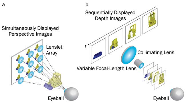
Figure 2. Near-eye 3D displays. Light field display (a). Temporal-multiplexing-based multiplane display (b). Courtesy of Wei Cui.
On the other hand, a multiplane near-eye display projects 2D images at a variety of depths in front of the viewer and renders the image intensity at each plane according to the dioptric distance of the point from that plane along a line of sight to create continuous depth perception. To form images at multiple depth planes, most current techniques rely on temporal multiplexing4,5,6. This strategy employs a high-speed projector, such as a digital micromirror device (DMD), to generate a series of 2D images (Figure 2b). After the images are collimated, they sequentially pass through an acoustic lens5 or deformable mirror6, which rapidly varies its focusing power and projects the correspondent image to the desired depth. Although these images are displayed in sequence, the viewer still perceives a continuous depth cue if the volumetric image refresh rate is higher than the flicker-fusion threshold (60 Hz).
Nonetheless, this method faces a fundamental trade-off among the image dynamic range, the number of depth planes, and the volumetric display rate because the product of these three factors cannot be greater than the maximum binary pattern rate of the DMD. For example, given a typical DMD’s maximum binary pattern rate at 20 kHz and six depth planes displayed at a volumetric image refresh rate at 60 Hz, the dynamic range of each image is limited to only six bits (64 gray levels).
To solve these problems, a research team from the University of Illinois at Urbana-Champaign developed a computational 3D display, which they call the optical mapping near-eye (OMNI) 3D display8. The OMNI display has only recently become possible thanks to the convergence of advances in optical fabrication and digital processing techniques, which bridges the realms of applied mathematics, optics, and high-performance computing. Based on a spatial multiplexing architecture, the researchers simultaneously map different portions of a display screen to various depths while forcing their centers to align. These intermediate-depth images are then collimated by an eyepiece and projected onto the viewer’s retina.
Operating principles
The operating principle of an OMNI display is shown in Figure 3. A high-resolution 2D image is displayed at an electronic screen. The image consists of several subpanels, each targeting a designated depth. The workhorse of an OMNI display is a 4f optical relay with a spatial multiplexing unit (SMU) located at the Fourier plane. The SMU functions as a multifocal, off-axis Fresnel lens, adding both quadratic- and linear-phase terms to the incident wavefront. The quadratic-phase terms axially shift subpanel images to the designated depths, while the linear-phase terms laterally shift the centers of subpanel images to the optical axis. As a result, the subpanel images are mapped to different axial locations and laterally aligned at the output end.
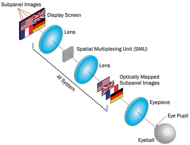
Figure 3. Operating principle of the optical mapping near-eye (OMNI) 3D display: spatial multiplexing unit (SMU). Courtesy of Wei Cui.
Finally, the light emanated from these intermediate depth images is collected by an eyepiece and enters the eye pupil. Depending on their relative axial positions, the viewer perceives these multidepth images at a distance from a near surface to infinity.
As an enabling component of the OMNI display, the SMU can be either a reflective or transmissive optical component. In their prototype, the researchers adopted a reflective configuration and employed a liquid-crystal-on-silicon (LCOS) spatial light modulator to act as the SMU (Figure 4). The light emanating from a high-resolution organic LED (OLED) screen passes through a beam splitter and is then collimated by an infinity-corrected objective lens. At the exit pupil, the team deployed an LCOS spatial light modulator to adjust the phase of the incident light. To map the subpanel images to the desired locations, they computed the required phase using a weighted Gerchberg-Saxton optimization algorithm and displayed it at the LCOS spatial light modulator. The reflected light is collected by the same objective lens, reflected at the beam splitter, and forms intermediate images at a variety of depths in front of an eyepiece. Owing to the unique optical mapping, the OMNI system can simultaneously display six high-resolution images (1000 × 1000 pixels) at a variety of depths. Moreover, unlike the temporal-multiplexing-based multiplane displays, the image dynamic range and the number of depth planes are decoupled from the volumetric image refresh rate in the OMNI display, allowing a high-dynamic-range (12 bits) 3D video displayed in real time.
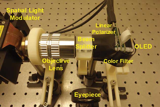
Figure 4. Optical setup of an OMNI display. Courtesy of Wei Cui.
The intermediate depth images in the OMNI display can be seen in a simple demonstration. At the input end, the letters U, I, U, and C are displayed in the four subpanels of the OLED (Figure 5a). The remapped letter images at these four depths are shown in Figure 5b to e, respectively.
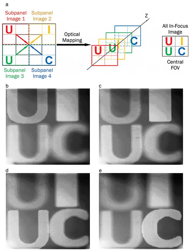
Figure 5. Visualization of depth mapping in an OMNI display. Mapping geometry (a). Images captured at four designated depths (b to e). Courtesy of Wei Cui.
As expected, the letters appear sharp at their designated depths but blurred elsewhere. To further test the OMNI in displaying a complex 3D scene, the designers generated the display contents at four nominal depth planes (spacing, one diopter) given an all-in-focus image (Figure 6a) and the corresponding depth map (Figure 6b). The depth-fused images captured at a far plane (zero diopters) and a near plane (three diopters) are shown in Figures 6c and 6d, respectively, matching closely with the ground-truth depth map (Figure 6b).
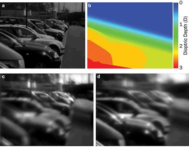
Figure 6. Three-dimensional display of a complex scene using an OMNI display. All-in-focus image (a), depth map (b), image focused at a far plane (c), and image focused at a near plane (d). Courtesy of Wei Cui.
It is noteworthy that although only the monochromatic scene was demonstrated, the OMNI display can reproduce colors. Using a white-light OLED as the input screen, a subpanel image can be split into three channels before covering them with a red-, green-, and blue-color filter, respectively. Accordingly, at the LCOS spatial light modulator, a phase pattern is shown to compensate for the wavelength difference, thereby mapping these filtered images to the same depth.
A compact OMNI 3D display method can provide the correct focus cues for a 3D scene, alleviating the vergence-accommodation conflict, improving the viewer’s comfort and wearing experience.
By following the human-centric design principle, such a technology holds promise for a new generation of 3D wearable displays and various VR/AR/MR applications.
Meet the author
Liang Gao, Ph.D., is an assistant professor of electrical and computer engineering at the University of Illinois at Urbana-Champaign, and has authored more than 30 peer-reviewed journal publications. He is a recipient of the NSF CAREER award in 2017; email: [email protected].
References
1. J. Jerald (2015). The VR Book: Human-Centered Design for Virtual Reality. Morgan & Claypool.
2. H. Hua and B. Javidi (2014). A 3D integral imaging optical see-through head-mounted display. Opt Express, Vol. 22, pp. 13484-13491.
3. D. Lanman and D. Luebke (2013). Near-eye light field displays. ACM Trans Graph, Vol. 32, Issue 6, article no. 220.
4. H. Xinda and H. Hong (2014). Design and assessment of a depth-fused multi-focal-plane display prototype. J Disp Technol, Vol. 10, pp. 308-316.
5. P. Llull et al. (2015). Design and optimization of a near-eye multifocal display system for augmented reality. OSA Imaging and Applied Optics, paper JTH3A.5.
6. X. Hu and H. Hua (2014). High-resolution optical see-through multi-focal-plane head-mounted display using freeform optics. Opt Express, Vol. 22, pp. 13896-13903.
7. O. Johannsen et al. (2013). On the calibration of focused plenoptic cameras. In Time-of-Flight and Depth Imaging: Sensors, Algorithms, and Applications, eds. M. Grzegorzek et al., pp. 302-317. Berlin: Springer, 2013.
8. W. Cui and L. Gao (2017). Optical mapping near-eye three-dimensional display with correct focus cues. Opt Lett, Vol. 42, pp. 2475-2478.</sup<>