JESSICA GEHLHAR, EDMUND OPTICS INC.
Calibration, pointing accuracy, and repeatability are critical to the success of vision systems for measurement. This is especially true for precise 3D multicamera measurement applications where single-pixel measurements are needed to help machine vision systems accurately gauge their environment. Even the smallest misalignment between optics and the components holding them in place will significantly affect the repeatability of 3D measurements.
Small, low-cost sensors and lenses and the ability to capture and store a lot of data have significantly contributed to the growth of 3D measurement. However, care must be taken to ensure that the vision systems’ mounting, alignment, and calibration do not change over time and affect performance. A combination of thoughtful lens design, sound manufacturing processes, initial calibrations, and dynamic in-the-field calibrations for camera system alignment is essential.
Up-front lens design
Although there are many factors to consider in lens design, there are several key considerations for multi-camera systems.
When specifying or designing the lenses for 3D imaging systems, their ability to maintain image center (or pointing accuracy) and constant magnification, operate at a constant ƒ-number, and maintain optimum focus are critical. The better the up-front design of the imaging lenses, the easier the manufacturing process, calibration, and software analysis will be.
Techniques such as removing adjustable irises, simplifying focus mechanisms, and gluing individual lens elements in place can make a lens more rugged and reduce the chances of key imaging parameters changing over time or because of mechanical shocks.
The focus can be simplified by replacing the nonrotating double-threaded barrel with a simple single thread and rigid locking mechanism, such as a clamp, nut, or set screws. This mechanical simplification and reduction of moving parts results in less flexibility, but it also can reduce costs.
In an imaging lens, the individual elements sit within the inner bore of the barrel. The space between the outer diameter of the lens elements and inner diameter of the barrel is typically less than 50 µm. But even small decenters of tens of microns are enough to significantly affect the pointing of the lens.
Ruggedizing a lens by gluing all of the individual elements in place prevents them from moving within the optical housing, which maintains pointing stability. When using a ruggedized lens, if an object point is in the center of the field of view and falls on the exact center pixel, it will always fall there even if the lens has been heavily vibrated (Figure 1).
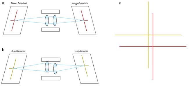
Figure 1. The unperturbed system where the object crosshair is properly mapped to the image crosshair (a). The perturbed system where lens elements are decentered within the barrel, changing the optical pointing stability and causing the object crosshair to be mapped to a different place on the image (b). Image crosshairs from 1a and 1b overlaid, showing the effects of lens decenter (c). Courtesy of Edmund Optics.
Athermalization by using different materials in the mechanics and optics also can make a significant impact by reducing focus changes over specified temperature ranges. Developing an athermal design is dependent on the optical substrate’s coefficient of thermal expansion (CTE) and its change in refractive index with temperature (dn/dT). For applications prone to temperature fluctuations, it is especially important for the optical system to be insensitive to an environment’s thermal change and resulting system defocus.
Additionally, optical systems are often designed in air, but the housing material is sensitive to thermal change. This should be addressed when considering an athermalized design. The expansion and contraction of a material because of temperature changes is governed by the material’s CTE, so careful consideration of the CTE of both the lens elements and their mechanical housing is required for athermalized designs.
Athermalizing optical designs is especially important for applications in the IR range. The dn/dT of most IR materials is orders of magnitude higher than those of visible glasses, creating large changes in the refractive index. If your application will experience significant temperature fluctuations, you need to understand the athermalization process of your imaging lens and how its performance will be affected by temperature swings.
Once an optimal aperture or ƒ-number setting is chosen, ensuring tight tolerances on the aperture diameter to maintain this ƒ-number is important. One reason some systems use multiple cameras is to offer different fixed apertures or focal lengths. In this case, using a lens with adjustable aperture leaves is unnecessary. This can be done as a part of simplifying the lens mechanics.
Using a fixed aperture with tight diameter and positioning tolerances will provide the most consistent results system to system. However, this comes at the sacrifice of some system flexibility, so fixed-lens apertures should only be used in systems that don’t adjust to the lens’ ƒ-number. Replacing an adjustable iris with a fixed aperture is ideal for applications where the system will be set up once and not changed afterward.
One of the key reasons to reduce the image variation system to system is to make stitching images easier and more accurate. For color systems, alignment of the color channels (typically red, green, and blue) simplifies stitching and other image processing steps. In systems with controlled lighting, using filters or monochromatic lighting is an effective way to avoid alignment error between color channels.
Daylight or uncontrolled lighting may be found in many applications where color data is required. For such applications, there is a benefit to using an optical design with relatively low chromatic aberration because this will reduce the blurring between color channels at the edge of the image. The amount of color separation can be modeled, but correction is difficult, particularly in embedded systems with limited image signal processing (ISP) flexibility.
Calibration
Understanding how to calibrate your lens and camera is especially important for 3D measurement systems.
There are many systems and software packages with complete distortion-correction algorithms already developed. The exact definition of distortion correction may vary from system to system. Some visual systems may not require calibrated distortion correction, and the distortion in each image may be based on subjective image-quality goals. However, most automated machine vision systems will need to gather accurate spatial measurements from the images.
Distortion is a monochromatic optical aberration that describes how the magnification in an image changes across the field of view at a fixed working distance. It varies with wavelength, so when calibrating distortion out of a machine vision system, the wavelength of the illumination needs to be taken into account. Distortion plots can be very helpful for this purpose (Figure 2).
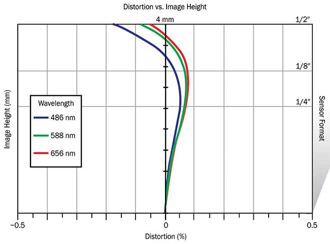
Figure 2. Distortion plot showing the variance of distortion between green, red, and blue wavelengths. Courtesy of Edmund Optics.
Distortion is typically specified as a percentage of the field height. In simple lenses, there are two main types: positive, barrel distortion, where points in the field of view appear too close to the center; and negative, pincushion distortion, where the points are too far away.
Distortion targets consisting of a grid of dots that are separated by various distances are used for calibrating imaging systems (Figure 3). Distortion can be calculated simply by relating the actual distance (AD) to the predicted distance (PD) of the image:

Magnification is an important but basic calibration that is usually combined with distortion calibration or focus. Any measurement system will require a magnification calibration, even if the lenses are designed as fixed focal length. Typical methods involve test targets and should be performed on already distortion-corrected images. For 3D measurement systems, triangulation must be performed on the final images, which will use magnification calibration or focal length approximations. The primary magnification of a lens is defined as the ratio between the sensor size and the field of view.
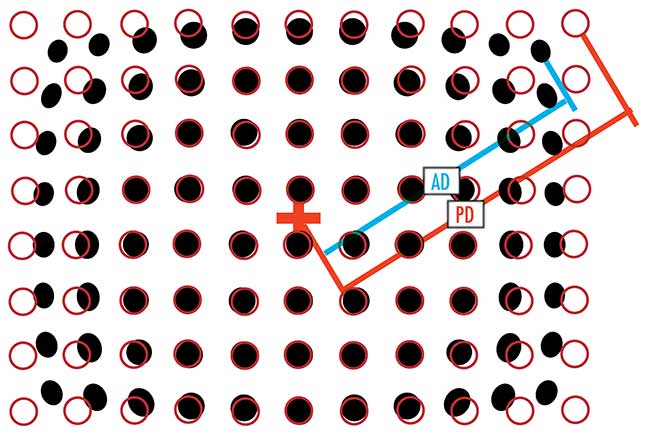
Figure 3. Calibrated target (red circles) versus true performance (black dots) dot distortion pattern. AD: actual distance; PD: predicted distance. Courtesy of Edmund Optics.
Monochromatic systems inherently have higher resolution than color systems because chromatic aberrations are eliminated and extra pixels are not needed for capturing different wavelengths. However, sometimes color is necessary for measurement applications where subtle variations of colors must be distinguishable. Typically, overall color response from the lens and sensor is examined during manufacturing tests to ensure color consistency from system to system. Overall camera- and lens-color calibration can also be a one-time factory setting made during routine color adjustments or white balancing.
Color-checker targets can determine true color balance of any color rendition system. They include patterns with an assortment of colors and act as a reference for testing and standardizing color inspection and analysis systems. Machine vision systems can be calibrated for color by measuring the systems’ RGB (red, green, blue) response to each of the reference colors and comparing the output to known values. A color-correction formula can minimize the difference between the known values and the measured outputs.
The final way to adjust for residual changes in performance over time is with dynamic (or per-image) corrections. Many algorithms are for scene approximation and other techniques for stitching or analyzing overlapping images for 3D measurement. Precise up-front hardware specification makes these on-the-fly corrections much easier and faster.
Meet the author
Jessica Gehlhar is a vision solutions engineer at Edmund Optics Inc. She received an imaging technology degree from Rochester Institute of Technology and has more than 12 years of industrial experience. She has designed and integrated a variety of imaging systems across many industries, including consumer device, medical device, pharmaceutical, energy, defense, and semiconductor; email: [email protected].