Through its heavy reliance on composites, the aerospace industry has grown accustomed to using adhesives. But automakers, with the exception of some in Europe such as BMW, are less comfortable with adhesives and it is up to machine vision to help build their confidence in this joining method.
Business has been getting stickier for Ron Weber, president of USS Vision, a Livonia, Mich., machine vision integration and automated inspection system firm. As automakers race to meet federal regulations that call for higher fuel-efficiency standards — 54.5 miles per gallon by 2025 — his firm is seeing more vehicles with body parts joined with adhesives. In recent years, that trend has translated into 11 percent annual increases in the adhesive bead inspection business offered by USS Vision, whose customers include GM, Ford Motor, Chrysler and Toyota.
“They’re using more of it because it [adhesive material] is superior than doing things the old way with rivets and bolts,” said Weber.
To ensure that adhesives are placed on a part’s surface in the precise location, without missing sections, and that each bead is the appropriate width and height, USS Vision uses a variety of machine vision cameras that are supported by its own proprietary software. Automakers’ increased use of adhesives has spurred USS Vision to buy more cameras, and recent years have seen several machine vision equipment manufacturers roll out systems specifically geared for bead inspection. But this inspection process is complicated by a host of factors such as bead shape and color, substrate color and reflectiveness, changes in factory lighting conditions and demand for higher throughput speeds.
“It’s not just a camera looking at a bead. There are a lot of variables,” said Weber.
Stronger adhesive, more composites
Between 2004 and 2014, the value of adhesives and sealant content in a North American light vehicles jumped 52 percent to $94, according to the American Chemistry Council1. Adhesives’ increased strength is one factor that is making this joining technology more appealing to automotive and aerospace manufacturers. For example, Düsseldorf, Germany-based Henkel claims its Teroson line of adhesives is 20 times more resistant to fatigue than riveting or welding.
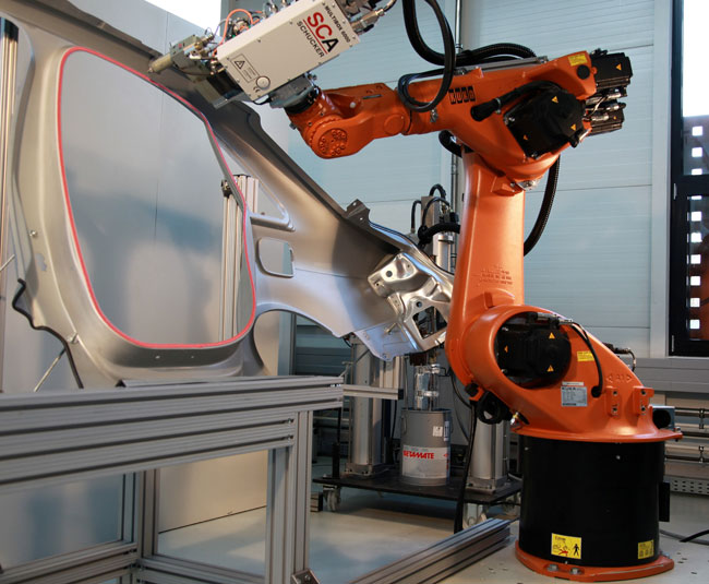
Figure 1. Structural adhesives enable automotive manufacturers to create lighter-weight vehicles by using a mix of dissimilar materials, including composites, aluminum and steel. The continuous bondline also adds structural rigidity, improves safety and helps seal the vehicle from dust and moisture. Courtesy of Dow Automotive Systems.
Another factor driving the increased use of adhesives is the increased use of carbon-fiber reinforced polymers (CFRPs), which are 70 percent lighter than steel and 40 percent lighter than aluminum, according to Plasan Carbon Composites, the leading U.S. Tier 1 supplier of CFRP parts and assemblies. Examples of Plasan’s CFRP body parts include the hood and roof for GM’s Corvette Stingray and the hood, roof and liftgate for Chrysler’s SRT Viper. Between 2004 and 2014, the value of plastic and polymer composite content in a North American light vehicle rose 50 percent to $430 (Figure 1)2.

Figure 2. BMW AG’s i3 was the first consumer vehicle to feature a predominately carbon-fiber reinforced polymer (CFRP) body. Courtesy of BMW.
Adhesives played an even more important role in enabling Munich-based BMW to develop its first mass-produced, all-electric vehicle — the i3 (Figure 2). Released in 2013, the i3 was the first consumer vehicle to feature a predominately CFRP body that was bonded with cutting-edge adhesives to structural mounts connected to an aluminum frame3. To accommodate for the i3’s mass production, BMW needed adhesives with accelerated hardening properties, meaning the glue had to be workable for only 90 seconds after being dispensed on a part and fully hardened within an hour and a half. The i3 featured 160 meters of bonded joints4.
Growing pains
Long before U.S. automakers felt pressure from the looming corporate average fuel economy (CAFE) standards set by the Obama administration and the pinch of higher gas prices, the aerospace industry in the late 1980s and 1990s had emerged as a pioneer in the lightweighting trend. Following the lead of the U.S. Air Force, which used CFRPs for its fighter planes, aerospace manufacturers began using these ultralightweight materials for tail sections and other primary or load-bearing sections5. In 2011, Boeing launched the 787 Dreamliner, the world’s first large commercial airliner with a predominately composite fuselage. Two years later, Airbus debuted its own commercial airliner with a predominately CFRP fuselage, the A350 XWB (Figure 3).

Figure 3. Airbus SAS’s A350 XWB features a fuselage predominately made of CFRP. Courtesy of TCHAIKOVSKI Artem — MasterFilms.
“The overall designs are being modified to reduce the number of fasteners where they can and replace with adhesive bonding as an overall weight savings,” said Ray Cornwell, a technical service manager for Henkel North America. Henkel’s adhesives are used by aircraft manufacturers such as Boeing, Airbus, Bombadier and Embraer.
Through its heavy reliance on composites, the aerospace industry has grown accustomed to using adhesives. But automakers, with the exception of some in Europe such as BMW, are less comfortable with adhesives, and it is up to machine vision to help build their confidence in this joining method, said Selamawit Belli, a marketing manager for Dow Automotive Systems. She pointed out that welding and mechanical fasteners have been with the automotive industry since its inception, and adhesives remain relatively new to it. Dow Automotive’s structural adhesives have been used in pioneering lightweight vehicles such as the i3 and Ford’s all-aluminum body F-150 pickup (see sidebar: “Laser Patterning Promises to Give Photonics a Role in Adhesive Composite Joining”).
“Welds and machine fasteners have gone through the growing pains that adhesives are going through,” said Belli.
Although Belli does not foresee U.S. automakers giving up steel entirely in car bodies, she said there are growth opportunities for adhesives. And just how much growth is dependent on the effectiveness of vision systems and their ability to inform OEMs of the presence, location and performance of the glue. However, she believes the machine vision systems currently available could do a better job at adhesive bead inspection.
“Quality is critical in the automotive industry, and in-line process control is an important element of many quality control programs. Although adhesives are used extensively today, the ability to verify proper surface preparation and adhesive application prior to joining could help enable further growth,” said Marc Benevento, managing director of Industrial Market Insight, a Columbus, Ohio, business improvement consulting firm. He is working with the Adhesive and Sealant Council on its automotive market development.
Cornwell said adhesive inspection with machine vision systems is currently “not a big issue” in the aerospace industry, but it will become more important as line speeds and part throughputs increase.
Adhesive bead inspection basics
Adhesives are predominately used for what is referred to as the body in white (BIW), or the assemblage of the vehicle’s body before it is painted. They’re also used in the “power train,” which encompasses the transmission and engine assembly. Pre-bonding bead inspection is critical because manufacturers currently cannot check the presence of an adhesive — or its strength — after the parts are bonded, though efforts are underway to develop or commercialize technology with such capabilities (see sidebar: “Lasers May Hold Key to Post-Bonding Adhesive Inspection”).
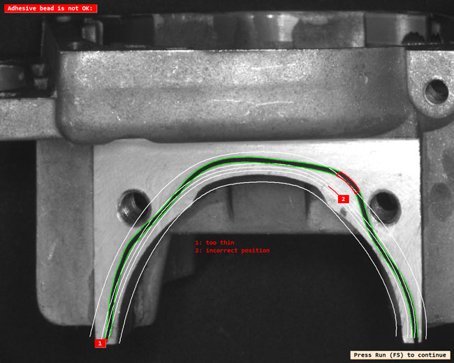
Figure 4. A typical bead inspection scenario showing a bead that is too thin in one place and in the incorrect position in another. Courtesy of MVTec Software.
Each manufacturer has their own quality philosophy that indicates when in-line inspection is required. Generally, safety critical parts, such as the white body and suspension, receive the most attention. Performing a vision check would be no different than using a torque wrench to make sure bolts are properly tightened,” Benevento said.
Generally, vision-based bead inspection is a two-step process. The first step is training, or the operator’s selection of the bead path, and the second is measurement. After a bead course is set, the operator marks the bead’s inner and outer edges and defines its target width and permissible tolerance (Figure 4). The part with the bead must appear under the camera in the same position, making proper illumination crucial, according to Johannes Hiltner, HALCON product manager for machine vision software company MVTec Software GmbH. Reflective of the growing use of adhesives in the automotive industry, MVTec in 2014 added an adhesive bead inspection feature to its HALCON 12 software.
The biggest challenge for a software library like HALCON is the applicability to a huge variety of adhesive bead inspection tasks, taking place in various setups,” Hiltner said.
Inspections can either occur post-process, meaning after a robot dispenses the adhesive, or in-process, meaning while the glue is being dispensed. For post-process inspections, the dispensing robot usually moves away from the part. Then, if the part is stationary, it may be inspected by an array of fixed cameras, by pivoting or titling cameras that sequentially inspect checkpoints, or by a camera moved by a robot over the part. Robots can also be used to move the part, which is inspected by one or more cameras6. While relatively easy to develop, requiring a camera, a housing, cables and software, post-process systems add to cycle time, said Michael Mai, a research and development group leader for Darmstadt, Germany-based Isra Vision AG.
The inspection happens after the adhesive beads are applied. Depending on the handling of the part, you will lose at least one second. If you need to move your part in some position, it is even more. In the automotive industry, this is a big issue,” Mai said.
In contrast to 2D post-process inspection, an in-process system, such as Coherix’s Predator3D, is directly mounted around the dispensing nozzle providing 360-degree bead verification. Dwight Carlson, president and CEO of Coherix in Ann Arbor, Mich., was critical of 2D vision cameras, which commonly are used in post-process inspections, as being “temperamental” because of their sensitivity to changes in factory lighting conditions, and changes in part color requiring frequent adjustment. But system integrators who use 2D systems said they can adapt to those variables.
In the end you’re getting the same result,” said Starke Farley, a senior sales engineer for Integro Technologies Inc., which has used 2D inspection systems for transmission housings, engine assemblies, fuel pump assemblies, and steel door and truck panels. The company has also used a 3D system for power train inspections.
2D vs. 3D
Adhesive bead inspection specifications vary between automakers and for the parts being joined. Basic inspections achievable with 2D sensors include verification of adhesive presence, location, skips (gaps) and width. For many BIW applications, in which round beads are used, this 2D inspection approach can be used, even though their volume can only be estimated, said Mai. Integro, for example, uses an area scan camera by Cognex Corp. to conduct “there/not there” inspections on adhesive beads. For these tests, software compares a scan of a part without the adhesive to one with it (Figure 5). However, Mai said, for other BIW applications, such as the inspection of triangular beads for windshields and sunroofs, 3D sensors are needed for volumetric bead measurements.
 Figure 5. Image of an adhesive bead dispensed on part of an engine assembly line (a), and data indicating a skip (b). Courtesy of Integro Technologies.
To conduct adhesive bead inspections, vision-based systems rely on contrast between the glue and substrate. While adhesive manufacturers can supply OEMs with glues that meet certain color specifications, such as red or green, there is a cost penalty to enhance the capabilities of 2D vision cameras. CFRP body parts are usually black, making the use of black adhesives challenging, if not impractical. According to Coherix, this no-contrast inspection is impossible for temperamental 2D vision systems to function.

Figure 6. Isra Vision AG’s Beadmaster is a 2D, in-process adhesive bead inspection system with a color sensor, as opposed to the monochromatic one used in an earlier model, enabling high-contrast imaging, regardless of adhesive color and substrate. Courtesy of Isra Vision.
“It does add a challenge because any vision system, whether it is 2D or 3D, relies on contrast,” said Farley at Integro.
To better achieve contrast, regardless of the adhesive’s or substrate’s color, Isra Vision earlier this year introduced a 2D adhesive bead inspection system called the BeadMaster. Whereas an earlier version of this technology had a monochromatic sensor, the BeadMaster has a color sensor. It provides red, green and other channels that contrast to the glue, depending on its color (Figure 6).
Laser sensors
To avoid the hurdles posed by the need for clear contrast, some vision companies have started to incorporate lasers into their in-process adhesive bead inspection systems. Examples of such systems include Isra Vision’s SeamStar3D, Coherix’s Predator3D and Mannheim, Germany-based VMT Vision Machine Technic’s SpinTop 3D.
Our customers are demanding they know what volume is being dispensed at any time,” said Carlson, who, in addition to founding Coherix in 2003, founded Perceptron in 1981.
The Predator3D features four 3D sensors incorporating both lasers and imagers (Figure 7). Isra Vision’s SeamStar3D similarly features a multi-camera-laser sensor, and VMT’s SpinTop 3D uses only two infrared lasers. Pointing out that a gallon of structural adhesives can cost up to $500, Carlson stressed that it is important for manufacturers to monitor how much adhesive is being dispensed throughout the joining process.
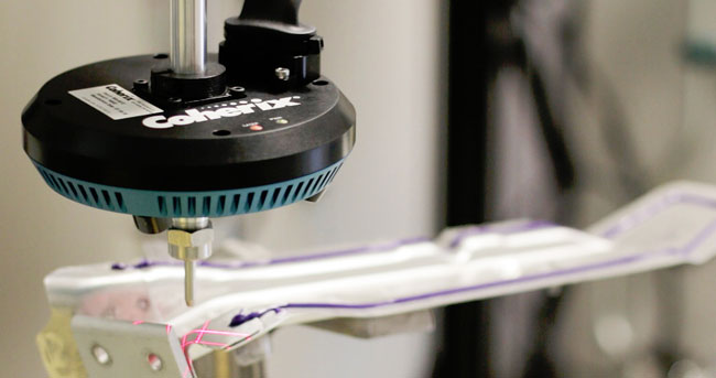
Figure 7. Coherix’s in-process adhesive bead inspection system, the Predator3D, inspects an auto part. Courtesy of Coherix.
While these in-process inspection technologies instantaneously determine bead volume and location, processing speed remains a challenge for companies such as Coherix. Carlson said his customers want to be able to dispense up to 1500 mm per second. However, Predator3D currently takes measurements on all four sensors at 400 times per second. Therefore, if the dispenser was moving at 400 mm per second, Predator 3D would deliver a 3D measurement every millimeter. However, if the dispenser was moving at 800 mm per second, Predator3D would be delivering a 3D measurement every 2 millimeters.
“To make the most of these technological advances, we also see a strong desire on the part of the composites industry to move these inspection systems from the end of the line, where they have traditionally been placed, back in-line with the process so that the information [that] machine vision supplies can be used to make process decisions that effect composite manufacturing production quality and speed,” Vanderbilt University mechanical engineering professor Douglas E. Adams said of machine vision systems for adhesive bead inspection in general.
James Schlett
[email protected]
References:
1. American Chemistry Council, Economics and Statistics Department (October 2015). Plastics and polymer composites in light vehicles. Plastics-car.com, white paper, p. 3.
2. Ibid.
3. L. Deptula and A. Noah (July 2015). Assessing the costs and benefits of effective lightweighting technologies. Center for Automotive Research, white paper, pp.10-12.
4. BMW (September 2013). A revolution in car making: BMW i3 production. BMW Media Information.
5. Huntsman. Lighter-weight composite airplane parts help aerospace industry lower fuel costs, white paper.
6. Isra Vision. Bead inspection — Postprocess. Products. www.isravision.com/likecms.php?site=site%2Ehtml&nav=173&siteid=241.
Lasers May Hold Key to Post-Bonding Adhesive Inspection
Three-dimensional machine vision systems assure automotive and aerospace manufacturers that the right amount of a structural adhesive has been dispensed on a part that will be joined with another. Such systems also confirm that the bead is complete, has the right shape and is in the right place. But what happens after the parts are joined is largely left to chance.
“You want to make sure the parts went on correctly,” said Selamawit Belli, a marketing manager for Auburn Hills, Mich.-based Dow Automotive Systems.
Unfortunately, adhesive bead verification does not translate into proper joining, and vision-based technologies are at a loss for testing bond strength. Belli pointed out that adhesive bonds may not satisfy OEM specifications if the parts are not properly mated or pressed together. During the mating or pressing processes, for example, the adhesive on a substrate could get scrapped off by the part with which it is supposed to join. In such cases, the visual adhesive bead inspection is essentially voided. More importantly, the structural integrity of the vehicle or aircraft made with this insufficiently bonded part could be compromised. Deficiencies with the adhesive itself could also result in a weak bond. Weak adhesive bonds are generally considered to be those that are less than 20 percent below the bond’s nominal strength1.
“Once they’re joined together, they’re bonded. You can’t differentiate the two,” said Bradley Weber, general manager for Datalogic Automation’s machine vision business. Datalogic’s technology has supported adhesive bead inspection for companies such as Mitsubishi Electric and Tata Motors in India.
Currently, the primary way automotive and aerospace manufacturers can verify the integrity of an adhesive bond is by tearing apart the joined pieces. Ray Cornwell, a technical service manager for leading aerospace adhesive manufacturer Henkel North America, said that in contrast to automakers, who typically use vision systems to inspect bead size and uniformity before bonding, aircraft manufacturers operate with slower production rates and typically inspect joined parts done after curing. The inspection technologies used on the larger aircraft parts, compared to those for automobiles, include x-ray, CT-scan or 3D measurement technology.
However, laser-based methods, such as laser ultrasonics and laser shock adhesion tests (LASATs) show promise as alternative nondestructive testing (NDT) methods.
Laser ultrasonics can survey an adhesive’s spread between joined parts and measure its thickness throughout an area by using a pulsed laser that generates ultrasonic waves in the sample. Those waves are then detected by a continuous wave laser receiver2. Almost a decade ago, Intelligent Optical Systems started a study funded by the U.S. Department of Energy on laser ultrasonics inspection of automotive body assembly adhesive bonds. The company developed a laboratory prototype scanning system, which was delivered to General Motors’ research and development division and could be mounted onto a robot. That prototype could accurately measure adhesive spread and thickness3.
“We had great success. Basically, we showed we could do what they [GM] needed,” said Marvin Klein, the study’s principal investigator and the manager of Intelligent Optical Systems’ Laser Ultrasonics Product Group.
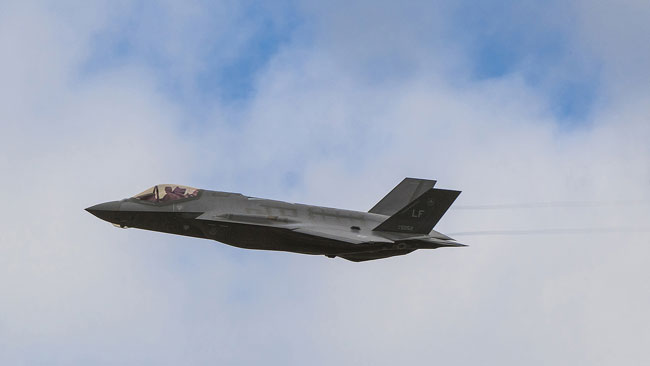
Laser ultrasonics is used to inspect composite panels
in fighter jets, such as the F-35 Joint Strike Fighter. Courtesy of Lockheed
Martin.
However, GM did not end up using laser ultrasonics for adhesive bond inspection because, in part, of budgetary concerns, Klein said. The measurement of bond strength remains the “holy grail,” he said. Although laser ultrasonics currently is not used for adhesive bond inspection, it is widely used for other applications. The National Research Council of Canada pioneered laser ultrasonics use in aerospace, followed by General Electric and Lockheed Martin. The technology has been used to inspect composite panels in fighter jets, such as Lockheed’s F-35 Joint Strike Fighter, and Airbus commercial airliners. Companies currently marketing laser ultrasonics systems for aerospace applications include Par Systems, Shoreview, Minn., and Montreal-based Tecnar, according to Klein.
LASAT is a technique first demonstrated in 19804 and that only recently has been eyed as a nondestructive testing (NDT) method for adhesively bonded composites5. For this technique, a high-energy laser pulse is targeted on an adhesively bonded part, resulting in the formation of plasma on its surface and, consequently, a pressure on the material surface due to the plasma expansion. This pressure produces a shock wave that will become release or tension waves after reflection on the sample’s back face. This tension wave will proof test the adhesive bond. There is a correlation between the laser energy and the tensile stress, which provides insights into the bonding quality6.
The aerospace industry is particularly interested in using the LASAT technique for testing adhesively bonded composites, said Silvio Kruger, the senior research officer at National Research Council of Canada in Brossard, Quebec, which has spent the past decade investigating this technology. While studies have shown LASAT can be used to differentiate adhesion qualities, the technique also damages composite parts because that is where the maximum tensile stresses occur — not in the adhesive bond line7.
“There’s no other alternative, so we’re not replacing another technology. We’re replacing destructive testing,” said Kruger.
References
1. R. Ecault and B. Ehrhart, et al. (November 2012). Laser adhesion test for adhesive bonded CFRP structures. 4th International Conference on NDT in Aerospace.
2. U.S. Department of Energy (2009). Laser ultrasonic inspection of adhesive bonds used in automotive body assembly. Lightweighting Materials 2009 Annual Report, p. 10.12
3. Ibid., pp. 10.12-10.17
4. L. Berthe and M. Arrigoni, et al. (September 2011). State-of-the-art laser shock adhesive testing (LASAT). Nondestructive Testing and Evaluation, Vol. 26, pp. 303-317.
5. B. Ehrhart and R. Ecault, et al. (2014). Development of a laser shock adhesion test for the assessment of weak adhesive bonded CFRP structures. International Journal of Adhesives, Vol. 52, pp.57-65.
6. R. Ecault and M. Boustie, et al. (November 2013). Development of a laser shock wave adhesion test for the detection of weak composite bonds. 5th International Symposium on NDT in Aerospace.
7. B. Ehrhart and R. Ecault, et al. (2014).
Laser Patterning Promises to Give Photonics a Role in Adhesive Composite Joining
While the lightweighting trend is opening doors for laser manufacturing companies when it comes to the automotive and aerospace industries’ increased use of lightweight aluminum for body parts, the same is generally not true when it comes to ultralightweight carbon-fiber reinforced polymers (CFRPs). After all, aluminum can be welded by lasers, whereas composites are not conducive and cannot be welded with a thermal process, said Benjamin Woomer, automated solutions manager at Genesis Systems, a robotic systems integrator in Davenport, Iowa.
While composite use is growing in the automobile industry, only few inroads have been made in vehicle structural areas, said Jay Baron, president and CEO of the Center for Automotive Research in Ann Arbor, Mich. He called BMW’s all-composite-body i3 sedan “an anomaly … not generally recognized as a trend.” BMW’s strategy, which includes the exclusive joining of the i3’s body with structural adhesives, may be more relevant in 15 years,” Baron added. In the meantime, industry watchers predict a mixed material approach — exemplified by General Motors’ Cadillac CT6 — will likely dominate in the U.S.
One way or another, the Oak Ridge National Laboratory (ORNL) in Oak Ridge, Tenn., has developed a treatment process that promises to secure lasers a role in the joining of CFRP and aluminum parts with adhesives. Researchers there have introduced laser-interference structuring as an alternative to using adhesive pads, grit blasting and solvents to prepare composite surfaces prior to bonding.
Using a 10-Hz Q-switched Nd:YAG laser by Spectra-Physics Inc., the ORNL researchers created a laser interference power profile by overlapping at different angles multiple beams split from one onto a sample surface. This multiple-beam method, which is also known as direct laser interference patterning (DLIP), allows for the creation of microscopic dot, line or ring-shaped patterns between 1 and 500 nm, whereas a traditional single-beam laser ablation approach could only create shapes identical to the laser spot and between 0.5 and 1 mm1.
ORNL is not alone in wanting to use laser patterning to strengthen adhesive bonds. General Lasertronics, a San Jose, Calif., company that manufactures specialized laser ablation systems for aerospace, nuclear and industrial applications, has spent the past 10 years developing a new laser surface preparation process that is specifically designed for CFRP materials. From the very first tests, laser processed samples demonstrated improved fracture toughness, fracture mode behavior and repeatability of adhesive bonds in CFRP materials. This laser process also produced exceptional coating adhesion properties on CFRP materials.
Detailed analysis has shown that this process removes mold release residues, increases surface energy, generates beneficial chemical functionality, and creates a micro-texture — all in one pass. Lasertronics has continued with the development and testing of this laser process in collaboration with commercial and military aircraft programs, and the testing continues to this day. Lasertronics Vice President of Technology Development Robert Cargill said this technology has significant potential for both commercial and military aerospace applications.
Since the laser ablation process photoablates, or vaporizes, a few microns of the matrix phase of the composite substrate, this process can be characterized as a “photonic peel ply.” Peel ply is a conventional CFRP prebonding surface preparation technique in which a sacrificial outer layer of bonded material is peeled off the composite substrate to generate a clean surface for the bonding process. Using high-power, short-duration pulses of laser energy, Lasertronics photoablates composite substrates to a depth of approximately 5 μm, removing a thin layer of matrix-phase material without ablating or damaging the carbon or glass fibers at the surface of the CFRP substrate.
“Lasertronics ablation delivered bonds that were about 25 percent stronger than conventional surface prep with abrasives, but more importantly, cut in half the variability of the bonds. As you know, for manufacturing, this kind of improvement in consistency can have really significant value,” said Lasertronics Director of Business Development Jim Russell.
In 2010, researchers at the National Institute of Aerospace and NASA’s Langley Research Center, both in Hampton, Va., attempted single-laser-beam patterning of a CFRP surface. They said this method was “a novel and precise way to both clean a composite surface prior to bonding and provide a bond-promoting patterned surface akin to peel ply without the inherent drawbacks from the same.”2
Baseline picture aluminum and carbon fiber surfaces without laser structuring (a) and with laser structuring (b). Courtesy of Oak Ridge National Laboratory.
“Traditional one-beam laser rastering was used in the past to structure the surfaces prior to joining, but one-beam rastering limits the sizes of the laser-induced surface-structures to those of the beam size,” said Adrian S. Sabau, the senior research staff member of ORNL’s Materials Processing and Joining Group in the Materials Science and Technology Division.
By structuring the surfaces of the aluminum and CFRP with laser-interference structures, the researchers increased the strength, maximum load and displacement at maximum load of single-lap joint specimens by 14.8 percent, 16 percent and 100 percent, respectively, compared to baseline joints. The laser-interference structured surfaces also help the joints absorb 150 percent more energy than baseline joints. This increased energy absorption could help improve vehicles’ crash safety.
Sabau, who led the ORNL team, said the ORNL is looking to collaborate with Fraunhofer, which has also conducting pioneering work on DLIP for different applications. While cost of materials themselves is a factor that could slow the adoption of laser-interference structuring for the joining of lightweight materials with adhesives in the automotive industry, there may not be much else holding this technique back.
“The technology is here but the cost has to be estimated for each product in part. … In my opinion, the technology is ready to be implemented,” said Sabau.
References
1.A. S. Sabau and J. Chen, et al. (May 2016) A laser interference-based surface treatment of aluminum and carbon fiber polymer composites. Society for the Advancement of Materials and Process Engineering 2016 Conference.
2. M. A. Belcher and C.J. Wohl, et al. (May 17-20, 2010). Laser surface preparation and bonding of aerospace structural composites, SAMPE 2010 Conference, Seattle.