TIM DYKSTRA, CONCEPT SYSTEMS INC.
Manufacturing environments are busy places with multiple machines, bustling workers and numerous machine-human interactions. Avoiding collisions between robots and humans is a high priority. Some solutions require a multilayered approach, integrating a variety of technologies, to create a reliable system. As more manufacturers add robots, there’s an increased interest in ensuring they work safely with each other and with humans.
Leveraging techniques from stacker cranes
Companies that increase their use of robotic automation can learn from collision avoidance techniques used with cranes, which received early attention because a collision with equipment in the work environment or the component itself was unacceptable. This posed a serious safety hazard that could cost thousands of dollars in lost production time and rework or scrap. By using 3D vision and industrial computers, collisions are now largely avoidable.
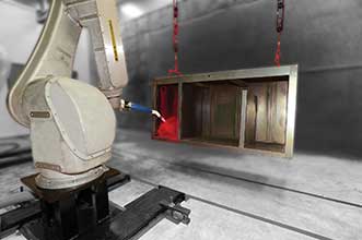
Manufacturers that deploy robotic painters, such as the one shown here, can use a multilayered approach that integrates a variety of technologies to create a system that reliably reduces the risks of collisions. Courtesy of FANUC.
As technologies advance, dramatic system improvements are possible. That was the case with Boeing, which found its floor-based registration system for painting planes no longer provided the accuracy it needed. As a long-time partner to Boeing, Concept Systems Inc. stepped in to assist the aircraft manufacturer in addressing this issue by deploying a new collision avoidance system.
A key component of the new system adopted by Boeing in one of its paint hangers was the proximity query package (PQP), which can detect imminent collisions between two computer-generated objects. Information about the exact size and shape of the plane is exported from Boeing’s design software and then rendered as a 3D graphic in OpenGL, a widely accepted open graphics standard. It similarly renders the stacker platforms for validation and troubleshooting the system.
To register the exact position of the plane in the hangar, a theodolite coordinate measurement system uses reflective stickers applied in specified places on the airplane to determine the exact position of the plane relative to the hangar and thus to the stacker platforms. This data, along with the information about the aircraft model and flap positions, are used to create a 3D computer rendering of the situation in the hangar. Then PQP is used to detect and avoid any potential collisions between the various objects.
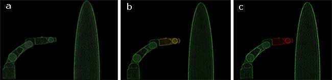
Images from the human machine interface (HMI) screen of a robot close to an object (a). As the robot gets close to the object, the color changes to yellow to show the warning zone (b) and to red in the halt zone (c). Courtesy of Concept Systems.
Inputs from the painters, using controls on the stacker platform, are run through a programmable automation controller (PAC), working in conjunction with a supervisory computer, known as a collision avoidance module (CAM). The CAM examines the movement requests and makes precise and complex decisions about what movements and speeds are allowable. Platforms can move within four inches of the surface of the plane, but no closer. The stacker platforms move more slowly as they approach the plane.
Using static collision avoidance in robots
Historically, many robots were hard guarded, locked down and required specific interfaces to access. Attention focused on preventing the robots from colliding, especially when they operated in a confined work cell. Collisions resulted in lost production, rework and waste.
Any robot purchased within the past five years uses standard communication protocols that inform other robots in a cell where it’s moving next. Industrial duty six-axis robots often include software that provides static collision avoidance, which works effectively when there is no variation in the robot’s tasks or workspace. This prevents the robot from crashing into fixed points in the cell.
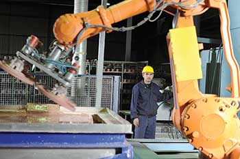
Industrial environments are becoming more dynamic as robots and humans increasingly interact on the factory floor. Collision avoidance systems are crucial to preventing not only injuries to workers or damage to products but also to minimizing automation downtime.
Moving onto dynamic collision avoidance
Now attention has turned to the interface between robots and their dynamic environment, whether that is changing a part, identifying fixture locations or interacting with humans. Many work environments are open, flexible and dynamic, with other machines and people in the same space as robots, which need to be able to anticipate a possible collision and avoid that situation.
Depending on the configuration of the robot and its components, it can actively make many decisions. The extent of those decisions varies depending on the function performed, so it’s important to consider what the robot will do today, as well as how it might need to adapt to complete future tasks. Contemporary robots do not rely on having every sequence, step or motion thought out and entered in advance. Many times, force sensors or vision systems will provide a robot with coordinate offsets to adjust their programmed paths.
There’s a movement toward making dynamic control more accessible and smoother. Due to the complexity of the calculations involved in dynamic control, a dedicated PC with more horsepower than the robot controller is capable of handling is often required.
Selecting 3D sensors based on application
Industrial robots in a 3D space need to adapt to variations in the physical environment to increase flexibility, utility and velocity. A number of technologies — specifically, commercial off-the-shelf (COTS) sensors — can help robots understand their surroundings in 3D space and allow them to prevent collisions with parts, fixtures and humans that may be moving around them.
Three-dimensional machine vision scanners, such as those developed by Cognex, Hermary Opto, Sick and Keyence, allow continuous scanning of stationary and mobile objects, making them ideally suited to collision avoidance applications. These sensors typically use conventional triangulation, and they output a point cloud. The output of multiple scanners can be stitched together to see complex shapes.
Stereo vision is another technology that can be used to help robots see changes in 3D space and prevent collisions. This technology relies on two conventional cameras that provide alternate views of a single object, similar in theory to how human binocular vision obtains two different views to create depth perception. In these applications, structured light or a known light pattern allows the machine to see how the light deforms, providing critical depth and surface information. The obvious negative of this technology is that it depends on external lighting conditions, which adds complexity.
Lidar, the technology used in many autonomous vehicles, has become more common in industrial environments. Velodyne Acoustics LLC, for example, has developed a lidar system with factory automation applications. It generates exceptional data for navigation algorithms and typically has a longer operating range than other vision technologies, which is critical for collision avoidance when there are changes in the environment, including interactions with people.
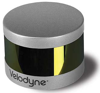
Lidar is becoming more common in industrial environments. Velodyne Accoustics LLC’s VLP-16 Lidar Puck, shown here, is an example of a lidar system with factory automation applications. Courtesy of Velodyne Accoustics LLC.
Lidar sensors can be selected to provide the degree of data accuracy needed. Two-dimensional sensors may be fine for an application that requires vision of a plane, while 3D sensors provide a more complete visual image. When selecting a lidar system, consider how far it needs to see, the degree of light sensitivity, the angular resolution required, the field of view, refresh rate and accuracy.
Light field cameras, such as those made by Lytro and Raytrix, are also gaining traction. This technology became available in the past few years, so the price point remains high. With this technology, several thousand or even millions of micro-lenses are placed in front of the image sensor and behind the camera’s “main” lens. This creates a vast number of redundant images, almost like having multiple stereo vision systems in one device. Some of the advantages of light field cameras are they don’t require additional lighting, they can see slightly around objects, and they can be digitally refocused after the image is taken. This technology is likely the future of commercial photography, and it’s expected that cellphone cameras will adapt this technology, bringing down the high production costs. This will translate to an increased use, so expect to see more of this technology on the plant floor in coming years.
Incorporating computers and collision avoidance software
Three-dimensional sensing technology continues to improve image quality and provide more data to analyze. Combined with faster, more powerful computers, it is easier and faster to store, process and analyze 3D images in real time while also providing decision-making ability for the robot to alter a path or prevent a collision.
The Boeing example above shows the significant role of computers in avoiding collisions in a dynamic environment. As more developers become familiar with what’s available, imaging will continue to improve. Computers will play more of a role in being smart enough and fast enough to help the robot adapt to its environment.
This vision technology provides the critical images required for collision avoidance, but it is computer processing that is making dynamic collision avoidance a reality. The core software functionality of a typical collision avoidance module PC will comprise the following:
• Ability to import 3D models of individual part assemblies.
• Direct interface with vision systems to manage location offsets of variable parts.
• Real-time monitoring of robot, crane or lift controllers to manage collision risk.
• Dynamic control management to slow/stop robots, cranes or man lifts prior to collisions.
• Stand-alone ability to check for potential robot-to-part collisions providing redundancy checks for conventional programming.
The dawn of collaborative robots
Various laser- and optics-based technologies keep large robotic work cells safe and stop equipment when humans enter dangerous zones. Three-
dimensional technology and collision avoidance software are being deployed to allow automation systems to adjust their preprogrammed paths when parts or other objects vary in position. Automation systems must be developed to interact safely and efficiently with operators, as more are brought into facilities.
Due to their flexibility, ease of programming and ability to operate in close proximity to humans, collaborative robotics are increasing in popularity. Many robot manufacturers are churning out new smaller and slower robots that can interact with humans. These robots rely more on not having enough force or speed to injure a person rather than avoiding collisions. Baxter, a collaborative robot developed by Rethink Robotics, was one of the first of these types and is often used in light industrial situations, such as packaging. These collaborative robots perform simple, repetitive functions, but they cannot do many of the more complex tasks that require moving faster or dealing with heavier loads.
Contemplating the future
Right now, many people are hesitant to work near a larger and faster robot. Over time, they will trust machines and sensors more, as they operate safely beside them. Autonomous vehicles will play a large role in this mindset shift. As people and safety organizations see that cars can be prevented from colliding with other cars and humans, the optical technology and advanced software will become more prevalent in the industrial world.
In the future, larger and faster robots will operate safely in collaboration with humans. By taking input from vision systems, such as a 3D laser scanner or lidar, and running code in the background, collisions will become a historical occurrence. Humans will be able to walk into a work cell without performing lockout/tag procedures or forcing the robot to come to a complete stop. Instead, the robot may slow down or alter its path based on sensor and software feedback. This dynamic collision avoidance environment will reduce overall downtime while ensuring the safety of the product, the machinery and humans.
Together, 3D vision and industrial computers will create the ability to perform real-time collision avoidance calculations for robots, vehicles, cranes or lifts in the work environment. These improvements in optics and software, combined with a new safety culture, will continue to drive the proliferation of robots into new industries that will benefit from the flexibility, safety and collaboration they bring to the job.
Meet the author
Tim Dykstra is a product sales manager with Concept Systems Inc. in Charlotte, N.C.; email: [email protected].