Most image-quality discussions center on resolution, which is thought to uniquely determine system performance. Resolution, however, is a more complex concept.
Gerald C. Holst, JCD Publishing
Camera resolution depends upon the optical blur diameter and the detector size. Schade combined these to create an equivalent resolution that is a function of Fλ/d where F is the focal ratio, λ is the average wavelength, and d is the detector size. In the spatial domain 2.44 Fλ/d is the ratio of the Airy disc diameter to the detector size. In the frequency domain, it is the ratio of the detector cut-off to the optics cut-off (Figure 1).
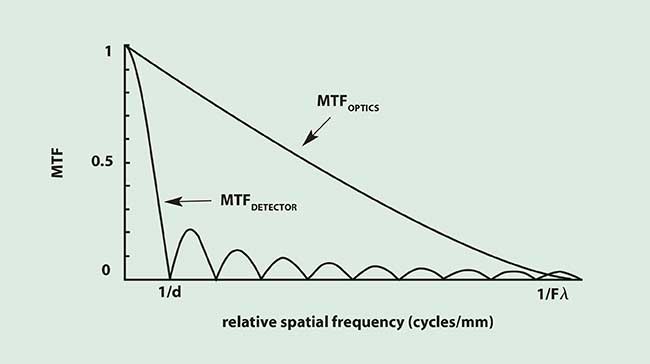
Figure 1. The system MTF is MTFSYS = MTFOPTICSMTFDETECTOR. Since the detector MTF dominates, this is a detector-limited system (Fλ/d = 0.1).
Understanding the two limiting cases is important (Table 1). For example, when operating in the detector-limited region, changing the aperture diameter does not significantly affect resolution. Conversely, when in the optics-limited region, changing the detector size has minimal effect. The transition from detector-limited to optics-limited is gradual and falls somewhere between 0.41 <Fλ/d <1.0.
TABLE 1.
DETECTOR-LIMITED VS. OPTICS-LIMITED PERFORMANCE
|
Fλ/d |
|
Resolution |
|
Spatial Domain |
|
Frequency Domain |
| |
<<1 |
|
Detector-limited |
|
Airy disc much smaller
than detector |
|
Optical cut-off much greater
than the detector cut-off |
| |
|
|
|
|
|
|
|
| |
>>1 |
|
Optics-limited |
|
Airy disc much larger
than detector |
|
Optical cut-off much less
than the detector cut-off |
Schade’s equivalent resolution
Schade introduced the concept of equivalent resolution. As a system approach, it combines the optics and detector MTFs:
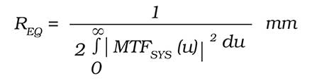
where u is the spatial frequency variable with units of cycles/mm. By using the square of the MTF, Schade emphasized those spatial frequencies where the MTF is relatively high. REQ cannot be directly measured. It is a mathematical construct that expresses system resolution. As the MTF increases, REQ decreases and the resolution “improves” (smaller is better).
The system resolution may be estimated from the subsystem equivalent resolutions by
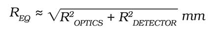
where ROPTICS = 1.845 Fλ and RDETECTOR = d. This approach allows us to analyze the optics and detector resolutions independently then to combine them into a system resolution. It is convenient to express the equivalent resolution as
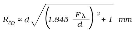
As Fλ/d decreases, REQ approaches d Light(detector-limited operation). For large values of Fλ/d, the system becomes optics-limited and the equivalent resolution increases. Matching the Airy disc (d = 2.44 Fλ) to the detector size creates an equivalent resolution that is 25 percent larger than the actual detector size (Figure 2). This image is slightly blurry compared to the detector-limited image and may be acceptable for some applications. In the optics-limited region, the imagery definitely appears blurry compared to detector-limited imagery.
CCD cameras
The detector size in a typical 1/2-inch format CCD array is about 10 μm. Since they operate in the visible region of the spectrum, the average wavelength is 0.5 μm. Reducing the focal ratio below two does not significantly improve resolution because the system is operating in the detector-limited region (Figure 3). The mathematical approach allows values that are neither physically realizable (e.g., F = 0) nor practical (e.g., F = 50). We must select the region of applicability. However, these extreme values indicate the limiting performance in the detector-limited and optics-limited regions.
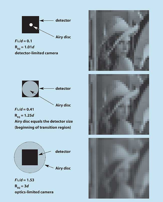
Figure 2. Imagery created by MAVIISS for three different Fλ/d ratios.
Thermal imaging cameras
Consider, for example, a longwave infrared (LWIR) camera. The typical LWIR detector size is about 25 μm. The average wavelength for this spectral window is 10 μm. Because the Airy disc diameter is equal to the detector size when F = 1.02, LWIR cameras tend to be optics-limited (Figure 4). Since the wavelength is significantly longer, LWIR cameras cannot provide the same resolution or image sharpness as a CCD camera.
Range performance
Although the detector-angular-substense is often used to calculate the maximum range, it provides an overly optimistic range because the optics resolution has not be considered. As a summary metric, REQ provides a better indication of system performance than a single metric such as the detector size or blur diameter. Therefore, a more realistic measure of range performance is
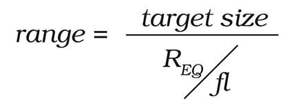
As the focal ratio increases, the optical blur increases and detection range decreases (Figure 5).
System design
The optical designer can select aperture diameter and focal length. Detectors generally are available in only a few sizes and the system designer has a few choices. The system approach creates an optics-detector combination with the appropriate Fλ/d. Although we strive for diffraction-limited optics, this is not essential when operating in the detector-limited region. Optics with minimal aberrations is acceptable as long as the blur diameter is sufficiently smaller than the detector size. Simply stated, better-quality optics may not necessarily provide better resolution.
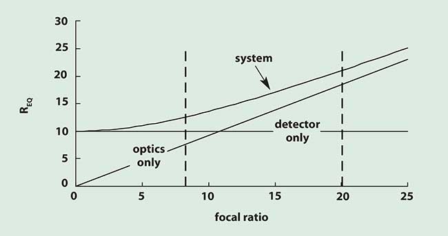
Figure 3. Equivalent resolution for a typical 1/2-inch format CCD camera (d = 10 μm). Detector-limited operation is to the left of the vertical dashed line at F = 8.2 (Fλ/d = 0.41) and optics-limited is to the right of F = 20 (Fλ/d = 1.0). With practical optical systems, the minimum focal ratio is about 1.0 with a theoretical limit of 0.5.
However, care is necessary. If the same optics are placed on a camera with smaller detectors (moves into the optics-limited region), then the aberrations may become objectionable. Note that we are specifying a camera system with particular optics-detector combination (Fλ/d). Any other combination may not provide the desired performance.
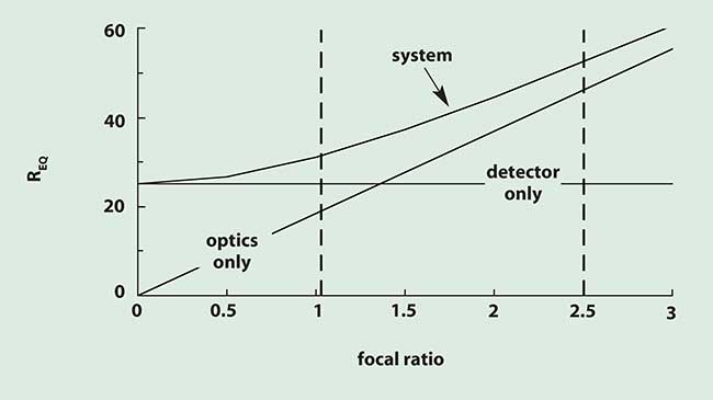
Figure 4. Equivalent resolution for a typical LWIR camera (d = 25 μm). Detector-limited operation is to the left of the vertical dashed line at F = 1.02 and optics-limited is to the right of F = 2.5. Note different scales on both axes in Figures 3 and 4.
This is a world in which smaller is better. Detector sizes are shrinking, allowing the system designer to create smaller cameras. However, this places a burden on the optical designer. For example, replacing a 1/2-inch format array with a 1/4-inch format array requires a 2× reduction in the focal ratio to reduce the equivalent resolution by 2×. Furthermore, sensitivity is proportional to (d/F)2. If the detector size is reduced by 2×, the focal ratio must also decrease 2× to maintain the same sensitivity.
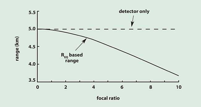
Figure 5. Detection range for a 1-m target using a 1/2-inch format CCD camera with a fixed 50-mm focal length lens. The aperture diameter decreases as the focal ratio increases. The atmospheric transmission is assumed to be unity.
System design has a number of competing requirements. For minimal aberrations, a high focal ratio lens system is generally desirable. For maximum sensitivity a low focal ratio system is the design choice. For maximum range performance it would seem that a long focal length lens is required. For fixed aperture diameter, this means a high focal ratio; but, a longer focal length lens will not increase range performance in the optics-limited regime.
This analysis describes resolution as a function of the ratio Fλ/d. Figures 3 through 5 illustrate performance for specific cameras where the wavelength and detector size are fixed. System performance graphs will look different depending upon the variable selected (e.g., varying D with fixed fl compared to varying fl with fixed D). No matter what variable is selected, the imaging system will eventually become detector-limited or optics-limited. While the MTF and equivalent resolution approaches provide the mathematics to describe system performance, they do not provide imagery.
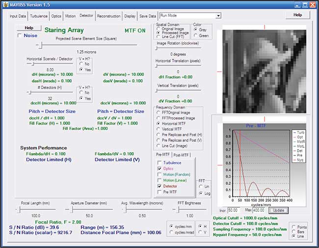
Figure 6. Graphical user interface for MAVIISS setup for 1/2-inch format CCD with 50-mm lens. The MTF in the lower right is identical to Figure 1 and the imagery is identical to Figure 2 (Fλ/d = 0.1).
Equally important, but less obvious with general imagery, are sampling artifacts. Edge ambiguity and phasing effects are described in Detector Arrays: Taming the Irregular Shape Problem. Sampling effects are accentuated with periodic patterns such as bar targets (USAF 1951 target) and bar codes. MAVIISS simulates all imaging systems ranging from low-fill factor to over-sampling created by super-resolution algorithms for any input scene. Its feature-rich graphical user interface (Figure 6) allows a user to easily and quickly navigate in the system design trade space. The values of important parameters are controlled by slide bars. Because of its fast execution speed, MAVIISS provides nearly fluid imagery changes as important parameters are changed.