Understanding the fundamental characteristics of scatter and the limitations imposed by scatterometers is essential to performing meaningful stray light calculations.
Richard Pfisterer, Photon Engineering LLC
Except for direct illumination from the sun, laser, or other light source, everything we see or detect is ultimately scattered light. Light can be scattered or rescattered during its propagation to our eyes or to a detector by rough surfaces, textures, and particulates. This scattered light is essentially “optical noise.” Consequently, the calculation of signal-to-noise (SNR) frequently involves scatter as both desired signal and undesirable noise.
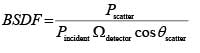
Mathematically, scatter is expressed as a bidirectional scatter distribution function or BSDF. The BSDF is defined as
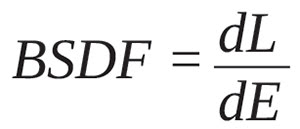 where dL is the differential radiance produced by a surface being illuminated by a differential irradiance dE. (Another way to think about this is to consider dE to be the input and dL the output where BSDF is the transfer function.) However, the term “scatter” in BSDF is a bit misleading because any radiance function is valid. For example, even an ideal specular (mirror) reflection has a BSDF whose functional form is a delta function.
It is a common misconception that BSDF is a percentage of scattered power and as such is unitless. But this cannot be true by virtue of its radiometric definition; BSDF has units of inverse steradians.
BSDF can have all kinds of dependencies and so calculations can become complicated very quickly. Virtually all materials exhibit an angle-of-incidence dependence. (Most people have observed that a nonglossy surface such as a tabletop becomes very specular at grazing incidence.) The physical processes responsible for scatter have strong wavelength dependences, particularly in the visible. (In the longwave IR, on the other hand, virtually every material is specular because the wavelength is large relative to the surface texture.) Some surfaces such as diffraction gratings or other ruled surfaces have different scatter characteristics in different directions; this is called anisotropic scatter. Scatter can be polarized by, for example, propagation through the atmosphere, which is why polarizing filters are used in photography to create a deep blue (as opposed to a washed-out) sky.
Given its definition, a BSDF can’t be negative. And while it is theoretically possible for it to be exactly zero in a given direction, it’s never been observed. However, it is possible for a BSDF measurement to be exactly zero, but this would be due to a scatter signal dropping below the sensitivity of the scatterometer.
From a theoretical standpoint, BSDF also obeys the principle of reciprocity; that is, the energy flow from the incident direction into the scatter direction is the same if the directions are reversed (for example, the incident direction becomes the scatter direction and vice versa). While rooted in the concept of conservation of energy, reciprocity is rarely observed in actual BSDF measurements. There are several reasons why this happens in practice: differences in how the surface and/or subsurface is illuminated by the scatterometer in the two directions; localized BSDF anisotropy or structures in the sample; contamination during measurement; other instrumentation-related effects (drift, noise, etc.). Interestingly enough, BSDF measurements of highly specular samples are much more likely to demonstrate reciprocity than diffuse samples because the reflective coatings in the former case provide little opportunity for any significant subsurface scatter effects.
While BSDF itself may not be intuitively obvious, quantities derived from BSDF can be very insightful in practice. One such quantity is the total integrated scatter, or TIS, which is the integral of the BSDF over 2π steradians. The TIS has a physical meaning: It is the percentage of incident power that is scattered into the hemisphere. For example, a black paint may have a TIS of a few percent while a very specular mirror may have a TIS of nearly unity. (The blackest material, and hence the most perfect absorber, currently known is a carbon nanotube technology called “VantaBlack” whose TIS is an incredibly low 0.035%.)
Considering the physics of scatter, we recognize that scatter is not solely a surface effect. There are whole classes of materials such as marble and skin whose subsurface structure plays a significant role in the formation of the observed scatter field. For example, the amount of subsurface damage present in a mirror surface determines the relative amount of scatter in the near-specular direction (a mirror with considerable subsurface damage has less near-specular scatter than a mirror whose subsurface damage has been removed through a process such as acid etching). In marble, the surface scatter contribution gives the BSDF an angular “glow.”
As a natural extension of the concept of subsurface scatter, volumes can also scatter, and these are characterized by bidirectional volume distribution functions, or BVDFs. The natural world is replete with examples: We have all observed spectacularly colorful sunsets, the murky depths of a lake, and the diffusion of light by fog and smoke that are due to particulate scatter in a volume of media.
Types of scatter found in nature
While it is certainly possible to create a custom scatter function using, for example, holographic diffuser technology, nature seems to prefer five basic BSDF functions:
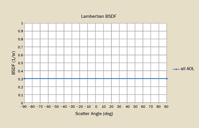
Figure 1. The BSDF for an ideal Lambertian scatterer shows no dependence on angle of incidence. Courtesy of Photon Engineering LLC.
The simplest BSDF is Lambertian scatter (Figure 1), whose BSDF is given by ρ/π where ρ is the hemispherical reflectivity or TIS. There is no angular dependence; the BSDF is constant for all angles of incidence and scatter. By virtue of its simple functional form, we can readily establish numerical limits on Lambertian BSDF: The maximum possible Lambertian BSDF is 1/π sr−1 or approximately 0.318 sr−1. Nature doesn’t seem to do this all that often and in fact, the only common example is thermal emission. (Commercially available SpectralonTM is commonly considered Lambertian, but only up to approximately 30° angle of incidence. At larger incident angles, the scattered S-state and P-states split and the P-state becomes rather reflective.)
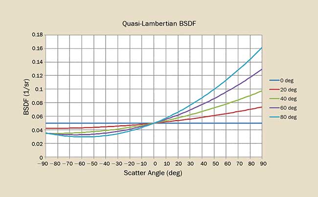
Figure 2. The BSDF for a quasi-Lambertian scatterer is ideally Lambertian at normal incidence then increases as a function of angle of incidence. Courtesy of Photon Engineering LLC.
Many materials such as paints exhibit quasi-Lambertian behavior (Figure 2). In this case, the scatter function is nearly Lambertian at normal incidence and increases with angle of incidence and scatter angle.
Diffuse scatter (Figure 3) is very much like quasi-Lambertian scatter except that it exhibits some gloss (localized angular increase in BSDF) at all angles of incidence. Diffuse (flat or matte) paint and plastic generally exhibit this property.
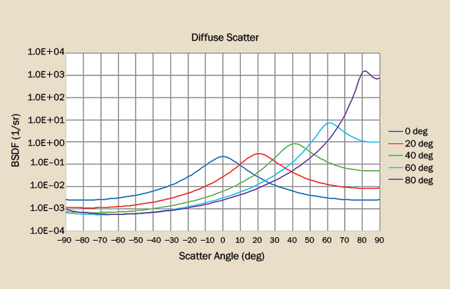
Figure 3. The BSDF for a diffuse scatterer shows a broad specular gloss at normal incidence and then increases as a function of angle of incidence. Courtesy of Photon Engineering LLC.
Specular scatter is manifest as a sharply peaked BSDF at all angles of incidence. Most of the scattered energy is contained with some relatively small angular spread. While specular BSDFs are commonly observed in mirrors, many anodize processes also produce highly specular surfaces (Figure 4).
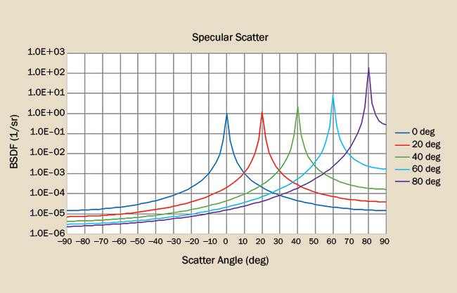
Figure 4. The BSDF for a specular scatterer is truncated Lorentzian-like function. Courtesy of Photon Engineering LLC.
Hybrid scatter (Figure 5) can be thought of as a combination of diffuse and specular scatter: At normal incidence, scatter is largely diffuse but becomes increasingly more specular with a greater angle of incidence. Many conventional surfaces such as tabletops, walls, and plastic parts exhibit this scatter property.
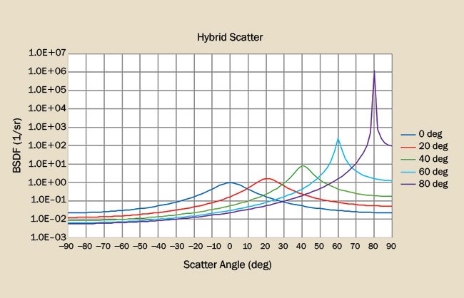
Figure 5. The BSDF for a hybrid scatterer shows a smooth transition from a diffuse scatterer to a specular scatterer as a function of angle of incidence. Courtesy of Photon Engineering LLC.
One might ask why the BSDF of an ideal specular reflection (a delta function) is not on this list. The reason: It isn’t observed in nature. Even the best mirror surfaces have some angular scatter around the specular direction.
Measuring scatter
Unlike length that can be easily estimated by inspection, BSDF can only be determined through a measurement, the most common of which involves a laser source, beam conditioning optics, a precision goniometer, a sample mounting stage, and a detector (Figure 6). The laser illuminates a small area of the sample under test with power Pincident; the sample is rotated so that the laser beam is incident on the sample at a given angle θincident. A detector is located at some distance from the sample, thereby subtending a solid angle Ωdetector. The detector is scanned over an angular range, (typically −90° to 90° relative to the sample surface normal), and at each specific angle θscatter collects power Pscatter. At each measurement point, the BSDF can be calculated as
 This measurement process may be repeated at different wavelengths (by using different lasers) or with different incident polarization states in order to more completely characterize the behavior of the BSDF.
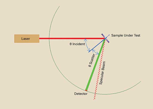
Figure 6. A laser, a sample mounted on a stage, and a detector mounted on a goniometer are the basic components of a scatterometer. Courtesy of Photon Engineering LLC.
Common problems in gathering scatter measurements
It has been said that even completely inaccurate calculations become validated if generated by a computer. The same can be said for scatter measurements. Completely erroneous BSDF measurements are routinely used by analysts because they were generated by a scatterometer. How can the scatterometer incorrectly measure a BSDF?
Like many measurement instruments, scatterometers have instrument signatures that limit how close to the specular direction it can correctly measure the BSDF. With the effects of diffraction from the interrogating laser beam and associated aberrations, as well as the physical dimensions of the detector, most scatterometers can accurately measure the BSDF no closer than a degree or so from specular. Instrument signature is particularly troublesome to BSDF measurements of very specular surfaces since most of the scattered power is in the near-specular direction.
The definition of BSDF calls for a differential area on the sample surface to be illuminated. In practice this is impossible to accomplish because even a laser beam occupies some area; the spot will always have a nonzero dimension. Changing the angle of incidence exacerbates the problem because the incident beam is projected onto the sample, thereby increasing its area. Consequently, the measured BSDF is the averaged BSDF over the illuminated area. In cases where there are spatial variations in the BSDF on the order of the illuminated sample area, the measured values can be very misleading.
When measuring the BSDF of specular surfaces, it is very important that the sample be planar over the illuminated area. If the surface is not planar, then the surface will reflect the incident laser light into a solid angle that the detector will interpret as an angular spread in the BSDF. (An important BSDF validation test is to integrate the BSDF to determine the TIS. Since the TIS must be less than or equal to unity, any significant angular broadening of the BSDF will show up as an unphysically large TIS.) Almost certainly, the resulting BSDF will be invalid. This problem often appears when measuring the BSDF of the cylindrical inside surface of a lens barrel or gold-plated mylar tape used in spacecraft thermal insulation.
Another source of error encountered with high specular samples is the finite-sized detector itself. In operation, when the detector is moved through the specular reflection, the resulting measurement is a convolution of the detector’s angular size with the beam, thereby broadening the BSDF measurement. While this argues for very small detector dimensions (and consequently small detected power), this must be balanced by the need for optimized instrument SNR.
Typically, the BSDF of samples vary by several orders of magnitude, and so this sets a requirement on the sensitivity of the scatterometer. Measuring the BSDF of highly specular samples tends to require a larger dynamic range than measuring that of flat black paints, and so scatterometers designed for a particular class of problems may not be appropriate for others.
Stray light analyses make heavy use of BSDF measurements, so the accuracy of a given analysis is directly related to the characterization of the component BSDFs. Rarely is the BSDF of actual hardware measured because of the logistics and expense — you cannot easily put a 4-m-diameter mirror into a scatterometer. So, often, analysts must frequently make due with measurements of samples or published data. As with cooking, the results are dependent upon the quality of the ingredients.