Whether the job is splicing fibers together or connecting fibers to system devices, alignment is the key to success. This article explores the many ways to achieve that goal.
Paula Trindell, Tyco Electronics
Just as an electronic connector provides a pluggable connection between electronic circuits, a fiber optic connector provides an optical one. The goal is joining a fiber to a transmitter, receiver or another fiber with the lowest loss of optical power across the joint. Figure 1 shows a simplified example of fiber optic connections in a typical premises wiring application. This requires both fiber-to-device interconnections at the end points and fiber-to-fiber connections at patch panels and outlets.
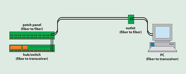
Figure 1. Fiber optics connects devices to patch panels.
The critical factor in a fiber optic connector or splice is alignment. The ideal connection will perfectly align the fibers, especially the light-carrying cores, so that the joint is transparent with no loss of optical energy. Unfortunately, both the fiber and connector are subject to manufacturing tolerances that create less than perfect alignment. Figure 2 shows typical causes of loss: All result from tolerance variations in the geometry of the fibers and connectors.
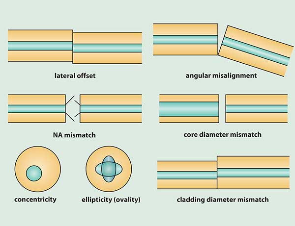
Figure 2. A variety of mismatches cause losses in a fiber-to-fiber connection.
Another cause is Fresnel reflections, which occur when light passes from one index of refraction to another, as from the fiber to air. In doing so, a small portion of light is reflected backward. In a connection where the mating connectors allow a gap between fibers, there will be a forward loss of about 0.32 dB, as well as a reflectance of –14.5 dB or return loss of 14.5 dB.
The good news is that both fibers and connectors are manufactured to extremely precise tolerances, which helps in aligning fibers mechanically. While there are other methods, such as using lenses to collimate and focus light, the dominant method is manufacturing a precisely placed hole in a precisely toleranced ferrule.
In evaluating a fiber optic connector, there are many performance characteristics to consider. Some are similar to electronic components such as temperature range, the ability to withstand shock or vibration, and durability (the number of times a connector can be engaged and disengaged). Insertion loss and return loss are the characteristics important to fiber optic systems that merit discussion here.
Insertion loss
Insertion loss expresses the reduction in optical power across the junction caused by applying a connector or splice. Insertion loss measurement, in simple terms, involves first measuring optical power through a length of fiber, cutting the fiber, applying connectors and remeasuring. The power through the fiber will be lower because the interconnection causes some loss of optical power.
Insertion loss (IL) is equal to:
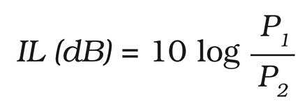 where P2 is power through the original (uncut) fiber and Pl is power through the connected fiber. Insertion loss is a concern because it reduces the optical power arriving at the receiver. Losses range from 0.01 for permanent fusion splices to 0.08 to 1 dB for connectors for glass fiber to 3 dB for connectors for plastic fibers. The new array connectors can even achieve losses as low as 0.15 dB typical.
Reflection loss
In single-mode systems, it is not desirable to have light reflect upstream toward the source. Even small reflections can influence the laser source, causing system noise. Therefore, it is important to reduce reflections so that reflected energy does not reach the source. Return loss refers to the reduction in reflected energy (compared with the incident energy). Greater loss is desired to minimize or eliminate the effects of reflected energy.
Because Fresnel reflections can be a significant source of reflected energy, one important way to reduce them is to ensure that the mating fibers touch. This often is done by having a slight radius on the ferrule. The type of end finish on the fiber/ferrule is called a physical contact, or PC, end finish. Angling the end face (an angled PC or APC finish) can further increase return loss.
Both the PC and APC end finishes also work to prevent any light reflected from being guided back toward the source. There are several levels of return loss in connectors (the measurement indicates how far the reflected power is below the incident optical power). Typical values for common nomenclature are as follows:
PC (physical contact): >30 dB
SPC (super PC): >40 dB
UPC (ultra PC): >50 dB
APC (angled PC): >60 dB
Because analog systems are most sensitive to reflection noise, they typically require higher return losses than digital systems. Analog systems most often use an APC end finish to achieve reflection losses of around 68 dB. A multimode system typically tolerates return losses of around 20 dB or less.
Terminating optical fibers
The traditional method of terminating an optical fiber involves preparing the fiber, epoxying it into the connector, crimping the cable strength members to the connector body, cleaving the end of the fiber, and polishing the end to a smoothness that enhances light transmission. The need for epoxy, in particular, is inconvenient because of its potential messiness, long curing times, and the need for equipment such as curing ovens and epoxy applicators. Epoxy, however, was long thought necessary to provide a stable, strong termination.
Newer, epoxyless connectors provide excellent retention, no significant degradation in optical performance, and a significant reduction in application time and cost. Some epoxyless connector designs also dispense with the need for polishing.
Control of the end-face geometry is important, especially in single-mode applications, to reduce reflections. Of all the factors involved in terminating a fiber optic connector, polishing is the most critical and the one most susceptible to error. Yet polishing is neither difficult nor mysterious. As the final step, polishing prepares the fiber to ensure that defects and nonuniformities in the fiber face or ferrule geometry do not degrade light passing across the joint. Other steps such as crimping are largely concerned with mechanically fixing the fiber in the connector.
Splices
While a connector is considered a semipermanent, pluggable connection, a splice is permanent. While some splices are re-enterable for repairs, they are made without the intention of even occasional connections and disconnections.
The most popular type is the fusion splice, where fibers are aligned and melted until they fuse. These offer the lowest losses, 0.1 dB or lower, but equipment costs make them most attractive for long-haul telecommunications where long fiber runs and the need for minimal losses justify costs. Fusion equipment is highly automated, positioning the fiber for the point of lowest loss.
Because fusion splicers are expensive, a large number of splices are needed to make fusion cost effective: At several thousand splices per year, the cost per splice can be considerably lower than for mechanical splices.
Mechanical splices, which are used for temporary or permanent repair and restoration work, offer a fast, easy alternative. While some mechanical splices are permanent and used for permanent splice points and for jumpers, others are re-enterable. Splices are usually fast and easy to apply with little specialized tooling.
Connector types
Connectors offer a disconnectable method for joining fibers to transmitters and receivers, other fibers and devices such as couplers and multiplexers (Figure 3). Most connectors are in the form of a cable-mount plug in which plugs mate with a feed-through receptacle that resembles a cylindrical coupling bushing. The inner diameter of the receptacle often has a split sleeve to provide a snug alignment of the mated plugs.
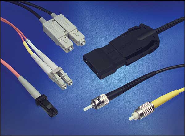
Figure 3. Popular fiber optic connectors based on the 2.5 mm ferrule.
Because connector size is a primary factor in port density, cable connectors continue to get smaller. Most of this gain comes from the use of smaller ferrules. The newer MU and LC connectors use a 1.25 mm diameter ferrule, exactly half the size of a 2.5 mm diameter ferrule used in traditional FC, ST and SC connectors. Also, MT ferrule connectors are being combined in high-density arrays. Table 1 gives typical values for popular styles of connectors, grouped by ferrule size:
LC Connectors: The fully standardized LC connector utilizes a 1.25-mm ceramic ferrule and the versatile, pull-proof RJ-45 latching mechanism. Available in single-mode, multimode, simplex and duplex versions, they offer low insertion loss, low back reflectance and repeatable performance.
MU Connectors: The MU connector is one half the size of the standard SC connector, and is sometimes referred to as the mini-SC. Featuring a push-pull latching mechanism similar to the SC, the MU connector is easy to connect and disconnect. It provides a single point of disconnect in high-density applications, a feature often required by telecom operators.
TABLE 1.
CHARACTERISTICS OF INDUSTRY STANDARD CONNECTOR TYPES
|
Ferrule
Size |
|
Connector
Family |
|
Coupling
Mechanism |
|
Single-Mode
(typical fiber) |
|
Multimode
(typical fiber) |
|
Fibers per
Connector |
|
Applications |
| |
|
|
|
|
|
|
|
|
|
|
|
|
|
| |
2.50 mm |
|
ST |
|
Bayonet |
|
√ |
|
√ |
|
1 |
|
Premises cabling,
Ethernet &
Token Ring,
networks, telphony |
| |
|
|
|
|
|
|
|
|
|
|
|
|
|
| |
2.50 mm |
|
SC |
|
Push/pull |
|
√ |
|
√ |
|
1 - 2 |
|
Premises cabling,
ATM, low-cost
FDDI, Ethernet
& Token Ring,
networks, telephony
& CATV |
| |
|
|
|
|
|
|
|
|
|
|
|
|
|
| |
2.50 mm |
|
FC |
|
Threaded |
|
√ |
|
Not typical |
|
1 |
|
Telephony & CATV |
| |
|
|
|
|
|
|
|
|
|
|
|
|
|
| |
2.50 mm |
|
FDDI-MIC |
|
Latch |
|
√ |
|
√ |
|
2 |
|
FDDI, premises cabling |
| |
|
|
|
|
|
|
|
|
|
|
|
|
|
| |
mini |
|
MT-RJ |
|
Latch |
|
√ |
|
√ |
|
2 |
|
Premises cabling,
ATM, Ethernet
(10 Mb/s to 10 Gb/s)
|
| |
|
|
|
|
|
|
|
|
|
|
|
|
|
| |
1.25 mmi |
|
LC |
|
Latch |
|
√ |
|
√ |
|
1 - 2 |
|
Telecom networks,
CATV, broadband
|
| |
|
|
|
|
|
|
|
|
|
|
|
|
|
| |
1.25 mm |
|
MU |
|
Push/pull |
|
√ |
|
√ |
|
1 - 2 |
|
Transmission
equipment, patch
panels, ODF, and
and networking
|
| |
|
|
|
|
|
|
|
|
|
|
|
|
|
| |
MT |
|
MPO |
|
Push/pull |
|
√ |
|
√ |
|
4 - 72+ |
|
Data centers,
premises zone
cabling
|
| |
|
|
|
|
|
|
|
|
|
|
|
|
|
| |
MT |
|
LIGHTRAY
MPX |
|
Push/pull |
|
√ |
|
√ |
|
4 - 72+ |
|
Backplanes, telephony
|
SC Connectors: These emerged in the early 1990s as the general-purpose connectors of choice and are the recommended interfaces for premises cabling, ATM, Fibre Channel and low-cost FDDI. SC connectors use a 2.5 mm ferrule, push-pull locking mechanism and pull-proof design that prevents a slight pull on the cable from pulling the ferrule out of optical contact. Single connector plugs can be snapped together to form multiposition connectors.
ST Connectors: Originally developed by AT&T, they use quick-release bayonet couplings. A key ensures consistent, repeatable mating with the coupling bushing. They are available in a range of variations including ceramic, polymer or stainless steel ferrules and epoxy or epoxyless style termination. ST connectors remain the most widely and broadly used connector type.
FC Connectors: Used mainly by the telecommunications industry from which they derive, they use threaded couplings and 2.5 mm ferrules. Some variations of the connector use tunable keying to achieve the lowest loss. Tuning allows one ferrule to be rotated in relation to the other to minimize losses. The connector is keyed so that connectors will always mate in the tuned position.
FDDI-MIC Connectors and ESCON Connectors: Designed to meet the specifications of the ANSI X3.166 FDDI PMD (physical medium dependent) document, this duplex connector uses a side-latching mechanism and two 2.5 mm ferrules, as well as a fixed protective shroud to protect the ferrules. The connectors can be keyed according to fiber distributed data interface (FDDI) specifications, and also can be used for non-FDDI applications.
ESCON connectors, used in IBM ESCON channel interfaces, are similar to the FDDI-MIC connectors, but use retractable shrouds.
Plastic Fiber Connectors: These are available at low cost for fast termination to the cable, even at the expense of low loss. Most connectors require no epoxy, allow end finish to be achieved by trimming the fiber with a hot knife, and require little or no polishing.
Performance is in the 1 to 3 dB range. Many designs tend to be proprietary, although several standards have evolved using plastic fibers and connectors. Standardized applications include MIDI and digital audio, automotive and industrial automation. Many plastic fiber connectors incorporate LEDs and detectors directly as a means of reducing cost, simplifying the system and providing standardized parts.
MT-RJ Connectors: The MT-RJ is a two-fiber connector that resembles a standard telephone plug. The resemblance is intentional, as the connector is aimed at replacing the ST and SC types in wiring closets and at the desk. The connector fits in the same cutout as an RJ-45 jack, allowing fiber to be installed in network equipment, patch panels and wall plates without space penalties. The connector features a single, snagless latch. Rather than the typical fiber mating scheme that uses two plugs joined in a coupling adapter, the MT-RJ connector offers a true plug-to-receptacle mating technique. Plugs on the patch cable plug into a jack on the panel or faceplate. Fibers are terminated directly to the back of the jack with an epoxyless and no-polish termination.
High-Density Array Connectors: Multifiber array connectors such as LIGHTRAY MPX and MPO, and fiber-ribbon cable have been gaining in popularity (Figure 4). MT-style connectors, which use a small ferrule to hold 4, 8, 12 or 72+ fibers, provide the high-density interface required for high-bandwidth communications.
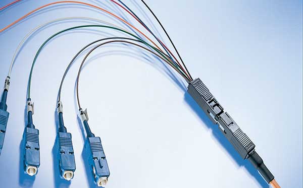
Figure 4. LIGHTRAY MPX array connector with hermaphroditic latching. LIGHTRAY MPX is a registered trademark of Tyco Electronics.
These connectors are used mainly in fiber arrays that replace the rat’s nest of coaxial cable associated with mainframe computers. They offer a neat, compact and orderly method to connect equipment.
These arrays are typically fanned out with jumper cables terminated in standard connectors, such as an ESCON duplex connector, to form the interface to the system equipment.
MT-style connectors point to an important trend in high-density interconnections. The array connectors are about as small as a modular telephone plug connector, but feature up to 72+ high-performance fibers on 250 µm centers in multiple rows. Guide pins on either end of the fiber rows help align the connectors during mating. The ferrule is precision-molded plastic with a temperature coefficient closely matched to the fiber’s.
Mating between fiber connectors is either a simple push-pull, or a hermaphroditic latching mechanism. The MPO connector was designed by Nippon Telephone & Telegraph of Japan, and since then, the MT ferrule idea has been adapted to a number of array designs, including a backplane version (LIGHTRAY MPX, developed by Tyco). One difference among designs is the overall size of the connectors. Connectors used inside boxes that will experience few mating cycles can be smaller and less robust than those used in patch panels with their frequent rearrangements.
The MT-style connector is available for both multimode and single-mode fibers with a flat end finish for multimode applications or an angled end finish for single-mode applications. The angled finish provides return losses of 60 dB or more without the use of index-matching materials.
Most array connectors are factory terminated. For most applications of array connectors, cable assemblies will be the preferred method. Many applications will require a large number of cable assemblies in short, known jumper lengths, while other applications will require custom lengths, particularly for longer interconnection distances. While field termination will probably be offered in the future, the ability to receive a ready-to-go, tested and characterized cable assembly is an obvious benefit.
High-density arrays will allow parallel or multichannel transmission. Used with low-skew cable, optical interconnections can offer skew and jitter figures in parallel transmission that are an order of magnitude lower than for copper counterparts. Such low distortion and absence of crosstalk mean greater signal integrity, especially at high speeds.
For multichannel transmission, arrays offer an ideal packaging method for achieving high performance in a tight form factor. Already demonstrated are 48-channel links operating at 2.5 Gb/s per channel, for an aggregate data rate of 120 Gb/s.
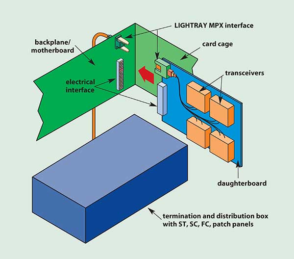
Figure 5. Array connector used for simplified backplane-based system packaging.
At such speeds, optical connections offer multigigabit bandwidth, increased I/O density, reduced crosstalk, simplified design requirements by reduced impedance control, and space and weight savings. Array connectors also can simplify packaging. Figure 5 shows a potential application in which an array connector is used to form an optical backplane. Several transceivers are connected through an array connector to patch panels.
Array connectors help create a new and simplified packaging technology. A PC board plugs into a backplane, making both the electrical and optical interconnection at the same time, and with the same convenience and ease.
Conclusion
Fiber optic connectors are available in a wide range of configurations. The choice of connector typically depends on the applications.
Connectors offer low insertion losses well within the reasonable demands of applications. Application speed, the required interface and special environmental or mechanical requirements may narrow the selection, but overall connector selection should be neither difficult nor tricky.