Understanding laser-induced contamination and UV fatigue of optics is critical to optimizing UV laser performance in any application.
MATTHEW DABNEY AND CORY BOONE, EDMUND OPTICS
Ultraviolet laser optics tend to have limited lifetimes, due primarily to two processes: laser-induced contamination (LIC) and UV fatigue. LIC is caused by the deposition of unwanted material on the surface of the optic, whereas UV fatigue results from the breakdown of the optic due to cumulative exposure to UV light. Both degrade the performance of optics over time until the effects become intolerable.
Long-term experiments on UV optics at 355 nm in various environments have revealed key insights into sources of contamination and fatigue, as well as mitigation strategies and cleaning techniques that can potentially recover contaminated optics.
What is laser-induced contamination?
Contamination of optics can occur when UV laser light interacts with particulates, water vapor, organics, and other contaminants in a system. These contaminants can come from the ambient air, optomechanics, and other materials in the system. Mitigating methods such as purging with dry nitrogen, though helpful, can still lead to conditions resulting in LIC1. Any buildup of particles can obscure the optical path, reduce component functionality, and potentially lower the laser damage threshold of the optics.
Condensation often occurs on optical surfaces due to low thermal conductivity. These condensed water molecules can then interact with the laser and surface material to cause LIC. Outgassing and other airborne molecular contaminants, meanwhile, can commonly lead to carbon-based deposition on optical surfaces. The dendritic growth of LIC can be observed in Figure 1.
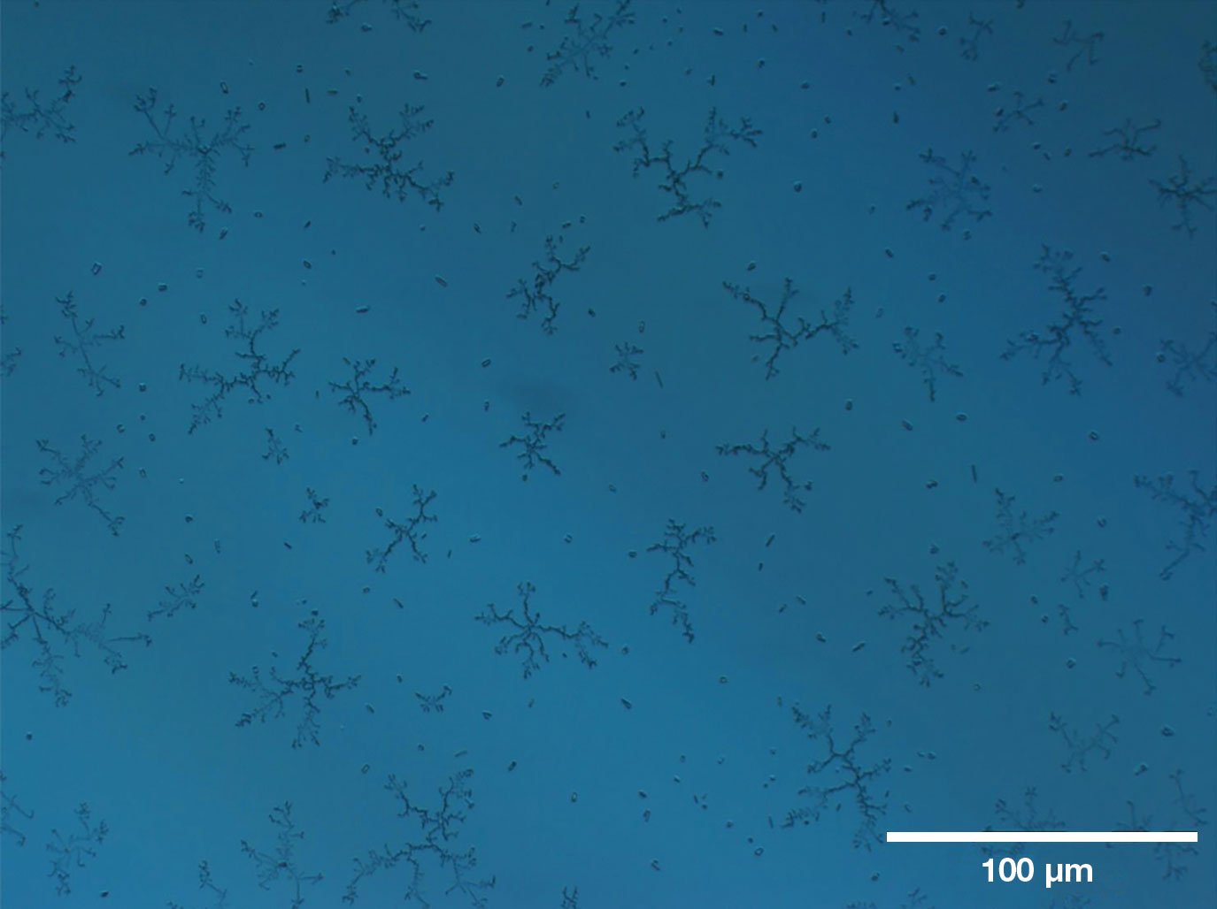
Figure 1. Example of UV laser-induced contamination (LIC) on an uncoated fused silica window after six weeks of ~3-W UV laser illumination. Taken with a microscope using a 10× objective, the image’s field of view corresponds to ~610 × 460 μm. See Reference 1. Courtesy of Edmund Optics.
Research conducted in 2005 helped detail the various laser interactions that lead to LIC2. Light-induced prenucleation, for example, involves a molecular layer building up due to the UV light interacting directly with the glass surface. The density of this buildup was shown to saturate at a certain level after a long-enough exposure time.
Interactions with surrounding gases can also lead to the deposition of contaminants. The photon energies of UV wavelengths <400 nm begin to approach the same scale as the bond energies of common molecules, such as O2, CO2, CO, N2, and others. This allows UV light to break down some of these bonds and create other ions and molecules that can contaminate optical surfaces.
What is UV fatigue?
In addition to the ambient causes of LIC, the materials that are used in coatings and substrates are susceptible to degradation over time due to the process of optical fatigue. This can occur even when the source’s intensity laser is below the laser-induced damage threshold (LIDT).
The concept of UV fatigue can be thought of like the binding of a book.
Numerous uses, even those that are gentle, will cause wear that will eventually lead to failure. UV degradation experiments performed by Edmund Optics have demonstrated the UV fatigue effect in certain situations, such as vacuum conditions. The differentiating characteristic between LIC and UV fatigue is that LIC is an additive process whereas fatigue is a breakdown of the material that causes discoloration or another intrinsic change, or possibly even the removal of material.
Two phenomena dictate the conditions and mechanisms causing this apparent reduction of optical performance that is below the single shot damage threshold in the short laser pulse regime. The first mechanism is based on a modification to refractive index, and results in a lensing effect that can increase the local intensity of laser light on an optic. The second mechanism involves the generation of optically induced defects through the formation of self-trapped excitons, which leads to the accumulation of absorption centers and the loss of optical efficacy.
Both LIC and optical fatigue can occur in lasers operating at visible and infrared wavelengths, albeit to a lesser degree. But the high energy of UV photons makes these effects much more prevalent in systems emitting in that spectral range.
The UV laser market has grown significantly in recent years and is expected to have a compound annual growth rate of 5.4% between 2022 and 2028, according to research firm MarketWatch3. High-power UV lasers have become critical for applications including lithography, medicine, micromachining, semiconductor processing, and additive manufacturing. LIC and UV fatigue cause the performance of these systems to degrade over time, requiring routine replacement of their optical components. This significantly increases the cost of maintaining UV laser systems, and degrading their throughput decreases system efficiency. The reduction of a system’s LIDT can also increase the chance of catastrophic system failure from laser-induced damage (Figure 2).
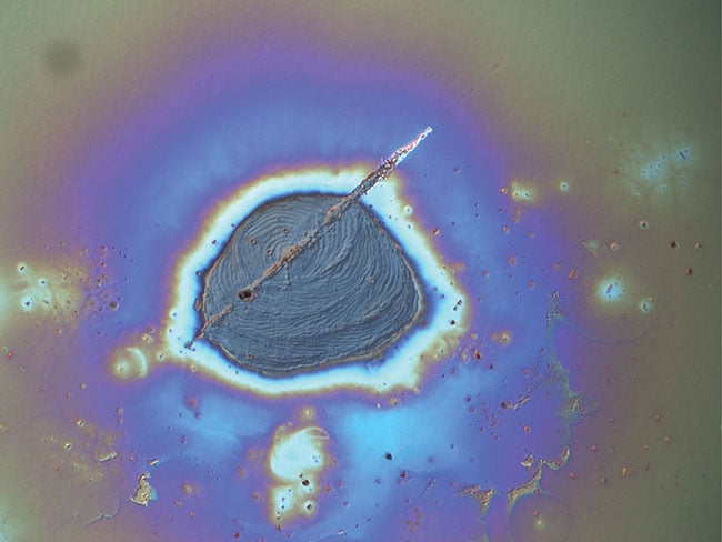
Figure 2. Example of laser-induced damage captured using a differential interference contrast microscope. Courtesy of Edmund Optics.
Analyzing LIC and fatigue
Experimentation has helped to simulate the degradation of optics in a UV laser system, investigate potential contamination sources, and explore different corrective actions. In one such study, a 355-nm, 10- to 20-ns pulse laser emitting ~0.6 mJ/pulse with a 0.6-mm beam diameter was used to experimentally analyze LIC and optical fatigue from UV laser exposure over time. The schematic for this testbed is shown in Figure 3.
The “burn box” consisted of several antireflective windows simulating how a laser assembly, such as a beam expander, would be affected by a UV laser system. The burn boxes enabled isolated experimental environments to be tested in parallel. Half-wave plates and polarizing beamsplitter cubes allowed for the control of the average power to each beam path of the experiment. A pair of matching energy meters measured average laser powers. This monitored the transmission reduction over time as the tested optics fatigued and/or became contaminated.
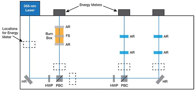
Figure 3. A schematic of the UV exposure testbed developed to simulate the degradation of optics in a UV laser system, investigate potential contamination sources, and explore different corrective actions. AR: antireflective window; FS: uncoated fused silica windows; HR: high-reflectivity mirror; HWP: half-wave
plate; PBC: polarizing beamsplitter cube. Courtesy of Edmund Optics.
Both daily and continuous measurements were taken. The daily measurements involved opening the enclosure to put an energy meter at each of the measurement positions shown in Figure 3, including those normally containing beam dumps, to make measurements for 3 min. The continuous measurements involved putting the two energy meters at the measurement positions outside the
enclosure, which normally contained beam dumps. The meters then recorded average powers every 30 min until the next daily measurement. An environmental chamber allowed for investigation of the discrete effects of various conditions, such as vacuum conditions or the presence of a gas. After each experiment concluded, an ex situ differential interference contrast microscope allowed researchers to view contamination on the surfaces of the windows.
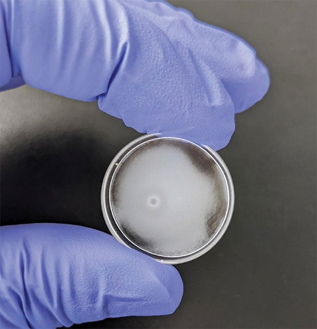
Figure 4. The opaque, white contamination shown here on a previously clear optic is the result of laser-induced contamination (LIC) from exposure to a UV laser. Courtesy of Edmund Optics.
General experimental findings
The burn boxes allowed isolated studies to be done in parallel and, more pragmatically, simulated laser optical assemblies such as beam expanders. Initial experiments revealed that the thread lubricants, anodized aluminum, and fresh Vitron O-rings used in many other types of optical assemblies were common sources of contamination in the UV system. Removing these improved the lifetime of the optics tested.
Viton O-rings: With fresh, out-of-the-package O-rings, the transmission of the burn box windows started degrading four days into testing and they became completely opaque after seven days. A milky, white haze formed on the contaminated optical surfaces after testing (Figure 4). Baking the O-rings before use prevented some level of outgassing, which resulted in 6% transmission loss during five weeks instead of complete transmission loss after one week. Placing the O-rings in a vacuum or simply letting them breathe in a clean environment was as effective as baking.
Anodized aluminum: Anodized surfaces contain pores, which trap contaminants that can be released later during use. Also, anodized materials can become reactive under UV exposure.
Stainless steel: Experiments using cleaned stainless steel instead of anodized aluminum led to no observable degradation after seven weeks.
Indium: A foil seal of indium provided superior resistance to UV degradation compared to O-rings.
Additional experiments are underway to test how the temperature of optics
contributes to the growth of LIC, or whether daily cleaning prevents contamination buildup, or whether blowing dry air over the system has any positive effects. The results of these experiments will be published as they become more conclusive. Further, these new experiments are looking beyond UV exposure at 355 nm to run tests at the 266-nm wavelength.
Summary
As many laser systems move toward shorter wavelengths to take advantage of higher energies and improved resolution, it will become more and more important to understand and mitigate UV fatigue and LIC. The experimental findings at 355 nm demonstrated that LIC could turn UV laser optics completely opaque in as short of a period as a week if traditional O-rings and anodized aluminum are used in the system. Thankfully, these effects can be significantly mitigated by swapping O-rings for indium seals, replacing anodized aluminum with stainless steel, and keeping the surrounding environment as clean as possible. When developing UV laser systems, talk to your optical component supplier for guidance on how make your system more resistant to LIC and UV fatigue.
Meet the authors
Matthew Dabney, Ph.D., is a principal R&D engineer at Edmund Optics where he runs the company’s in-house laser damage testing lab. Dabney carries over 30 years’ experience in the study of how lasers interact with different materials and has authored more than 30 published papers; email: [email protected].
Cory Boone is technical marketing engineer at Edmund Optics’ Woodcrest, N.J. office, where he manages the creation of technical content including application notes, published articles, video scripts, trade show materials,
case studies, and other literature; email: [email protected].
References
1. F.E. Hovis et al. (1994). Optical damage at the part per million level: the role of trace contamination in laser-induced optical
damage. Proceedings of the SPIE, Vol. 2114,
pp. 145-153.
2. H. Fosshaug et al. (2005). Some aspects on mechanisms responsible for contamination of optical components in DUV lithographic exposure tools. Proceedings of the SPIE, Vol. 5754, pp. 1601-1628.
3. MarketWatch 2023. UV lasers market is rising globally (2030), www.marketwatch.com/press-release/uv-lasers-market-is-rising-globally-2030-2023-06-15.
4. B.M. Arnold et al. (2022). UV fatigue of laser optics: laser-induced contamination. SPIE Digital Library, Vol. 12300.