The integrating sphere is a simple, yet often misunderstood, device for measuring optical radiation.
Greg McKee, Labsphere Inc.
An integrating sphere’s function is to spatially integrate radiant flux (light). However, before one can optimize a sphere design for a particular application, it is important to understand how an integrating sphere works. Integrating sphere theory originates in the principles of radiation exchange within an enclosure of diffuse surfaces. Although the general theory can be complex, it is easy to understand.
The concept, simply put, is this: The radiation exchange between two areas on the integrating surfaces is independent of the viewing angle and the distance between the surface areas. Therefore, the fraction of flux received by any point on the sphere wall is the same for any other radiation point on the sphere wall.
Sphere radiance
Light incident on a diffuse surface creates a virtual light source by reflection. The light emanating from the surface is best described by its radiance, the flux density per unit of solid angle. Radiance is an important engineering quantity because it can predict the amount of optical flux that can be collected by an optical system that views the illuminated surface.
For an integrating sphere, the radiance derivation considers the light introduced into the sphere, the sphere wall reflectance, the sphere surface area, the multiple surface reflections the light undertakes, and losses through the port openings. The light introduced into the sphere is near perfectly diffused by initial reflection. A fraction of light leaving the surface arrives at another surface area and is diffusely reflected, and so on. This radiant exchange occurs again and again until it is spatially integrated. The exchange in n reflections of the total flux incident over the entire sphere surface can be modeled in a power series and reduced down to a simple radiance equation:
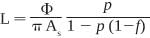
where Φ is the light introduced into the sphere, As is the sphere wall area, p is the sphere wall reflectance, and the f is the port fraction area. The simplified radiance equation can be used to model optical efficiency for light and LED measurement applications. These include optical attenuation for laser characterization, flux into a fiber or on the surface of a detector mounted on the sphere, spectral radiance for image sensors and spectral irradiance for nonimaging optical sensing sensors, or any one of the many radiometric and photometric parameters needed for integrating sphere applications.
Sphere multiplier
The radiance equation is purposely divided into two parts. The first is approximately equal to the radiance of a diffuse surface. The second is a unitless quantity that can be referred to as the sphere multiplier.
The sphere multiplier accounts for the increase in radiance due to multiple reflections. Figure 1 illustrates the magnitude of the sphere multiplier and its strong dependence on both the port fraction and the sphere surface reflectance.
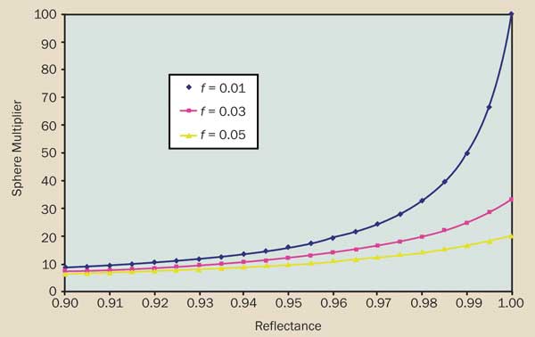
Figure 1. The magnitude of the sphere multiplier depends both on the port fraction (f) and the sphere surface reflectance.
A simplified intuitive approach to predicting flux density inside the integrating sphere might be to simply divide the input flux by the total surface area of the sphere. However, the effect of the sphere multiplier is that the radiance of an integrating sphere is at least an order of magnitude greater than this simple intuitive approach. A handy rule of thumb is that for most real integrating spheres (0.94 < p < 0.99; 0.02 < f < 0.05), the sphere multiplier is in the range of 10 to 30.
Spatial integration
An exact analysis of the distribution of radiance inside an actual integrating sphere depends on the distribution of incident flux, the geometrical details of the actual sphere design and the reflectance distribution function for the sphere’s coating, as well as all surfaces of every device mounted at a port opening or inside the integrating sphere. Design guidelines for optimum spatial performance are based on maximizing both the coating reflectance and the sphere diameter with respect to the required port openings and system devices. The effect of the reflectance and port fraction on the spatial integration can be illustrated by considering the number of reflections required to achieve the total flux incident on the sphere surface. The radiance produced after n reflections can be compared to the steady-state condition.
Since the integrating sphere is most often used in the steady-state condition, a greater number of reflections produce steady-state radiance as the sphere wall reflectance increases and the port fractional area decreases. Therefore, integrating sphere designs should attempt to optimize both parameters for the best spatial integration of radiant flux. Figure 2 is an image of a robotic imaging system used to map the spatial uniformity through an integrating sphere reference port.
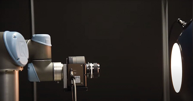
Figure 2. Integrating sphere spatial uniformity mapping.
Coatings
When choosing a coating for an integrating sphere, two factors must be taken into account: reflectance and durability. For example, if there seems to be plenty of light and the sphere will be used in an environment that may cause the sphere to collect dirt or dust, a more durable, washable coating or material can be chosen.
Items located inside the sphere, including baffles, lamps and lamp sockets, absorb some of the energy of the radiant source and decrease the spatial uniformity of the sphere. This decrease in spatial uniformity is improved by using a highly reflective diffuse coating on all possible surfaces.
The sphere multiplier is extremely sensitive to surface reflectance. The selection of coating or material can make a large difference in the radiance produced for a given design (Figure 3). Both coatings shown are highly reflective, over 95% from 350 to 1350 nm. Therefore, one might expect no significant increase in radiance for the same integrating sphere. However, the relative increase in radiance is greater than the relative increase in reflectance by a factor equal to the sphere multiplier. Although one offers a 2% to 15% increase in reflectance over the other within the wavelength range, an identical integrating sphere design would offer 40% to 240% increased radiance. The largest increase occurs in the near-IR spectral region above 1400 nm.
Baffles
In general, the light entering an integrating sphere should not directly illuminate either the detector element or the area of the sphere wall from which the detector is collecting direct reflectance. In order to accomplish this, baffles are often used in integrating sphere design. Baffles, however, will cause certain inaccuracies simply because the device is not a perfect integrating sphere. Light incident on a baffle does not uniformly illuminate the remainder of the sphere. It is advisable to minimize the number of baffles used in a sphere design.
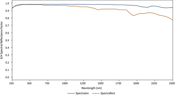
Figure 3. Typical spectral reflectance of two high-reflectance diffuse coatings.
Applications
The design of an integrating sphere for any application involves a few basic parameters. These include selecting the optimum sphere diameter based upon the number and size of port openings and peripheral devices. During the selection process for a sphere coating, spectral range and performance requirements should be taken into consideration. The use of baffles with respect to incident radiation and detector field-of-view and radiometric modeling to determine the coupling efficiency of an integrating sphere to a detection system should also be considered.
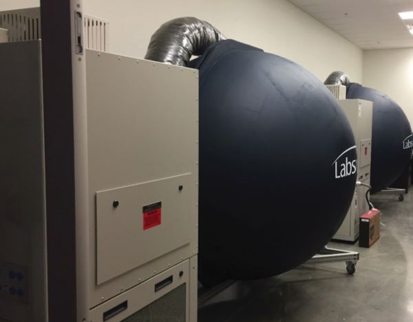
Figure 4a. Lamp measurement spheres built by Labsphere.
Lighting and LED spectral flux measurement
Perhaps one of the oldest applications for the integrating sphere is the measurement of total luminous flux from lamps. The technique originated at the turn of the 20th century as a simple and fast method of comparing the lumen output of different lamp types. Today, integrated sphere spectroradiometers are used to measure electrical, photometric, and radiometric performance of UV-VIS-NIR LEDs, general lighting, task lighting, portable lighting products, and more. Integrating sphere diameters for these applications can be as little as 5 cm and as great as 3 m or more (Figure 4a). Measurement of the total spectral flux and color of traditional and solid-state light sources of any size or shape is made more efficient by the use of an integrating sphere. Coupled with a spectrometer, the sphere can yield important spectral parameters such as spectral flux, chromaticity, correlated color temperature, CRI, TM-30, peak wavelength, and dominant wavelength, and more (Figure 4b).
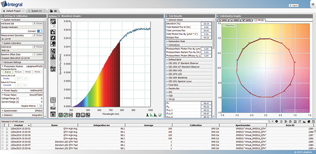
Figure 4b. Light measurement software.
Laser power measurement
A sphere can easily capture and integrate near-collimated sources such as laser beams or highly divergent sources such as laser diodes and VCSELs. Because of the unique geometry of an integrating sphere, radiant power measurements are independent of beam polarization and are nearly insensitive to beam alignment. A sphere can be designed for a wide variety of incident angles over a large area without affecting the signal at the detector (Figure 5). Additional ports can be added to perform a parallel spectral characterization, making it the ideal device for reliable laser diode life testing from DC to ultrafast lasers used in industrial applications.
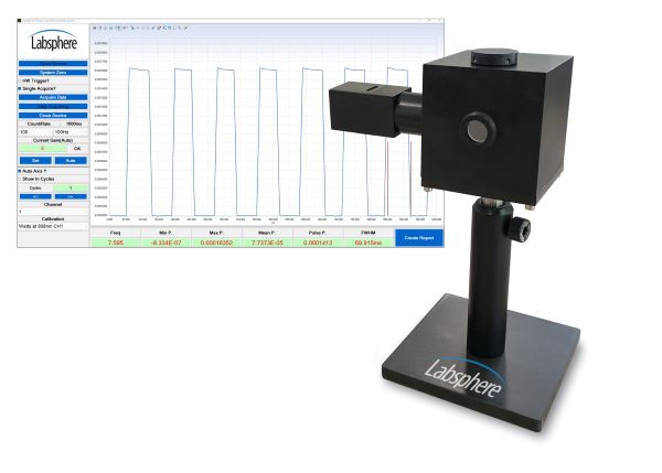
Figure 5. Pulsed laser power measurement system and software.
Imaging and nonimaging illumination
An integrating sphere is a near-perfect means for creating a uniform source of radiance or irradiance. Radiance is the flux density per solid angle leaving a source or radiant surface. Irradiance is the flux density falling upon a surface and is measured at the plane of the surface. The output aperture of an integrating sphere source, when designed correctly, can produce multispectral near-perfect diffuse and lambertian light source, independent of viewing angle even at angle exceeding 180 FOV with spectral tunability (Figure 6).
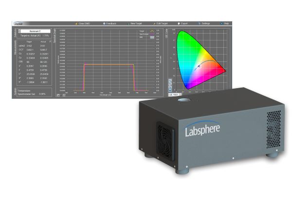 Figure 6. Spectra-UT ultra tunable test and calibration reference sources.
Reflectance and transmittance
The single largest use of integrating spheres is the measurement of reflectance and transmittance of diffuse or scattering materials. These measurements provide simple, quantitative characterization of materials such as thin films, architectural glass, and turbid liquids. In reflectance measurements, the sample and reference materials are mounted externally at the sample port. The total reflected radiation is collected and integrated by the sphere, providing a signal to a baffled detector. In transmittance measurements, samples mounted on the sphere wall are irradiated by a source outside the sphere. The radiation that is received by the sample is then partially reflected, partially transmitted, and partially absorbed. The sphere collects and integrates the transmitted component, providing a signal to a baffled detector.
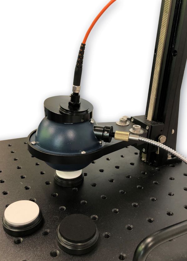
Figure 7. Reflectance/transmittance system.
The basic properties of the integrating sphere are easy to understand and form the basis of its versatility. Simply stated, integrating spheres operate as light collectors from which the collected light becomes either a source of illumination or is sampled for light measurement. Used as part of a radiometer or photometer, an integrating sphere can directly measure the radiant flux density originating from lamps, LEDs, or lasers.
The level of performance can range from acceptable to exceptional, depending on the quality of the components and design specifications (Figure 7).