Lighting, sometimes a step-child in machine vision considerations, has become a first-order consideration in automated applications.
SCHOTT North America, Inc., Fiber Optics
In the beginning, automated inspection focused on the camera and optics, the algorithms, the interface hardware and the processor. Only rarely was attention paid to the lighting system or lighting approach. As engineers became more familiar with lighting’s operating characteristics, the importance of lighting’s role became clear. Now, the many innovative approaches to lighting have helped to solidify machine vision’s value as an inspection process.
The focus today is on improving accuracy, process speed and reliability as applications become increasingly complex and difficult. To meet the challenge, cameras have become more sensitive, with millisecond responses; microprocessor speeds are in near real time and algorithms are approaching artificial intelligence levels.
Lighting has joined this metamorphosis, especially with the application of LEDs. Once the object of tinkering and experimentation, LED technology has developed into a viable solution for many machine vision applications. Underlying the success of LEDs are characteristics that had long distinguished fiber optic lighting as a preferred source, and a perception that they offer fewer of the less desirable traits — not the least of which is higher cost.
Of course, the other lighting technologies, lamp designs and power supplies have also evolved, but none has had the impact nor generated as much interest as the choice between fiber optic and LED illumination.
Fiber optic lighting
In this article, the term fiber optics refers to the optical fiber component and light source, commonly a 21-V quartz halogen, tungsten-filament lamp driven by a DC-regulated 150-W power supply. Fiber optic lighting systems can also transmit light from xenon strobes or metal-halide lamps, which provide intense output, near-perfect color and texture rendering, and/or short pulses (as fast as 1 µs) to freeze motion.
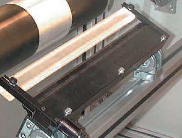
Figure 1. Fiber optic lighting works very well in aluminum web inspection because it can be shaped into a long, continuous, intense strip to illuminate the web completely.
Designers employ fiber optic lighting because they can shape it into different output configurations and can concentrate or focus the light in a particular profile at a precise angle to maximize contrast, increase speed, minimize false readings and yield optimum results from the inspection process. Optional lenses further enhance performance for most configurations.
When coupled with filters, optical fibers can eliminate or accentuate wavelengths, optimizing output for contrast control or preventing heat energy from "cooking" the subject. If the application is space-constrained, fiber optics can be designed to function in very small areas. Light transmission is possible in single fibers as small as 30 µm. If the application is in a high-temperature environment, fiber optics can function with a remotely located light source. Standard fiber optic lighting systems can tolerate ambient temperatures as high as 300 °C.
Specialized light sources or feed-back peripherals can maintain stable light intensity for the life of the lamp, minimizing the most significant variable responsible for false interpretation by a machine vision system.
Fiber lighting systems can maximize the uniformity of light output in the field of view, minimizing output variations of the lamp. When considering a broad range of applications, fiber lighting is best at providing the combination of intense, focused (or aimed), uniform light. It also has some drawbacks. Because it is a coupled system — that is, fiber optic components collect light at one end and disperse it at another — it is not optically efficient, losing at least 40 percent of the total light output. This loss increases over length, much like electron loss through a copper wire. Not only does output decrease, but attenuation of shorter wavelengths creates a color shift to the green/yellow end of the spectrum.
The typical illuminating lamp has a very short life (compared with the manufacturing process); thus, downtime (to change lamps) could pose a problem. Lamp output also drops during its life by as much as 15 percent. Therefore, if a process requires 100 percent light output, the lighting system will not provide sufficient output after several lamp-dependent operating hours.
Fiber optic components do not perform well in dynamic applications. Although special materials can improve the useful life of a fiber optic component, constant repetitive motion will fatigue the fiber, breaking it over time. In addition, glass and metal housings are heavy.
Manufacturing fiber optic components requires highly trained and experienced technicians. The products are custom-engineered to high-tolerance specifications and are hand-built, which introduces some variation in the final product. In addition, products are relatively low-volume, using specialized components that have long lead times. The result is that a precision lighting tool could be expensive and take weeks to build.
Solid-state source
LEDs have been around for decades. Historical data suggests that manufacturers improve output from these devices by 30 times every 10 years, so their application as lighting devices expands often. This drives diode costs down and generates even more interest in new applications.
LEDs have many of the same characteristics as fiber optics, and they can be configured in the same traditional arrays. LED lighting manufacturers have evolved several methods of shaping light. When coupled with a lens — either inherent in the individual, discrete LED unit or added to the component (surface mount or chip-on-board) — an LED can be aimed to create lighting angles and enhance contrast. LEDs are available in many colors, brightness values and focal lengths to add versatility.
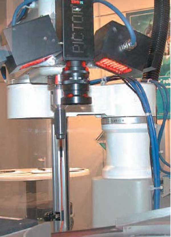
Figure 2. In a dynamic robotic inspection station, LEDs are the right choice because they last longer in applications where lighting is attached to a moving platform.
Because LEDs are small, electronic light sources, designers can combine circuit design and microprocessor control to create complex lighting configurations that interface with the inspection process. This enables very efficient inspection stations. LEDs are not as adaptable to space-constrained applications, but they can be used in small spaces.
LEDs are not nearly as bright as fiber optic systems, and manufacturers compensate for this short-coming by designing diodes to emit specific wavelengths (including IR and UV), matching their output to the camera or the application. They also can be pulsed in an overdrive mode, exponentially increasing output without greatly affecting long-term performance. Additionally, the pulse duration can be as short as 0.5 µs, 50 percent shorter than a xenon pulse.
The LED is a relatively stable light source, with a long, useful life. It is commonly accepted that single-color devices have a mean time between failures of 100,000 hours in continuous-use applications. However, poor design influences can reduce the package life to 20,000 to 50,000 hours — still a fairly impressive performance. An LED consumes less power than an equivalent fiber optic package, requires less maintenance and operates at lower costs.
With careful manufacturing and/or suitable diffusers/common lenses, LED lighting can provide good uniformity. However, the lenses found on discrete LEDs rarely aim the output on axis. This is not a huge issue when using components in general area-lighting applications, but it is if the lighting angle is critical. Each LED must be aimed to maintain the proper incident angle.
A motivated end user can quickly produce LED lighting products in-house with no specialized equipment. While not recommended (specialized manufacturers can do it better), this does make it easy to prove concepts and to create prototypes. Several LED manufacturers offer very responsive turnaround times for prototypes. LED lighting will last longer in dynamic applications (where lighting is attached to a moving platform), and it is better adapted than fiber optic lighting because of its lighter weight.
Intensity and color
Contrary to popular belief, LEDs do degrade over time like fiber optic light sources (Figure 3). A user can expect intensity to decline about 8 to 10 percent over the first 1000 hours and another 8 to 10 percent over the next 10,000. During this time, a color shift also takes place. Degradation and color shift are worse for white LEDs. A study at Rensselaer Polytechnic Institute Lighting Research Center in Troy, N.Y., found that 5-mm white-light LEDs had high lumen depreciation rates, reaching 50 percent of initial value after 6000 to 8000 hours. White LEDs are a relatively recent innovation; it was not so long ago that they were thought to be impossible to manufacture. White LEDs must overcome their problems so they can become more usable in the future. Because their color-rendering index is not good, they are only marginally useful for true color inspection (Figure 4).
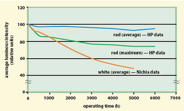
Figure 3. Contrary to popular belief, LEDs do degrade over time. Nichia data assumes that the diode operates at Tu = 60 °C, driven at 20 mA. The Hewlett Packard data assumes that the diodes operate at Tu = 55 °C, driven at 30 mA.
Because most machine vision applications are black and white, with peak camera sensitivity in the deep-red and IR range of the spectrum, the color shift is not a critical issue. (A red or other narrowband color LED would perform adequately.)
LEDs are well-suited to making small ringlights, spots and backlights. But making those configurations in large sizes (ringlights >4 in., spots >1 to 2 in. in diameter, backlights >4 × 4) is impractical. If more light is required, the LED lighting designer has two choices: Use high-output diodes or add more diodes.
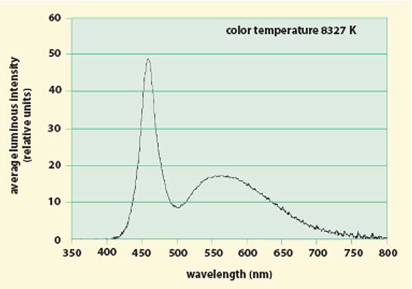
Figure 4. White LEDs use distinct sections of the spectrum to create their output. When analyzed, the output clearly shows one peak in the blue region, with very low concentrations of remaining wavelengths, created by phosphors. This makes them a marginal illumination source for true color imaging.
Adding more devices means an increase in both space requirements and heat generation. This reduces some of the output and increases the chance of premature failure. If the designer chooses to use high-output diodes, the required space does not increase as much, but heat rises dramatically. Some manufacturers use fans or water cooling to manage this problem, but this makes installation more difficult and increases the chances of premature failure.
Because LEDs are electronic components, they are not appropriate in wet or explosive environments. Furthermore, their maximum ambient operating temperature is 60 °C. Higher temperatures, humidity, exposure to high-power input, chemicals (acids, bases, saltwater, exhaust gas) and UV light can cause failure. Most LEDs are wired in groups. Therefore, if one LED in a chain fails, that failure accelerates failure of the entire group, which forever changes the intensity and uniformity of the product.
Manufacturers cannot precisely control the output from diodes made on different wafers. Therefore, LEDs should be sorted (or made from the same wafer) to match intensities; otherwise, uniformity suffers. Even sorted devices can vary by 15 to 20 nm in wavelength and 15 to 20 percent in intensity. If a failure occurs, matching output is very difficult. LEDs are less expensive to operate than fiber optics, but they are not necessarily less expensive to purchase. In fact, the costs may be even greater.
Which is best?
Neither fiber optic nor LED lighting technology exhibits all of the characteristics that would make it the perfect light source. For the foreseeable future, both technologies will have drawbacks that cannot be minimized or eliminated.
When designing or buying lighting equipment, consult a reputable supplier. Communicate all aspects of your application and ask the supplier to comment on alternative lighting types. Find out what emerging technology has to offer. Take advantage of the expertise of reputable suppliers of both LED and fiber optic manufacturers to optimize the solution for your application — and become enlightened!
Acknowledgments
The author would like to thank Nadarajah Narendran, director of research at the Lighting Research Center of Rensselaer Polytechnic Institute, and Axel Laschke, a physicist at Schott Glas, for providing insight and data for this article. In addition, several photonics professionals offered comments: John Merva, Northeast Robotics Inc.; Bill Thrailkill, Advanced Illumination; Patricia Katzman, PerkinElmer Optoelectronics; Paul Timson, Schott Fibre Optics; and Tom Bender, SCHOTT North America, Inc.