Freeform optics are enabling lighter-weight, high-performing systems. But their lack of rotational symmetry and rapid changes in curvature demand special manufacturing and metrology methods.
MARIE FREEBODY, CONTRIBUTING EDITOR
From applications in ophthalmology, endoscopy, and microscopy — to use in head-up displays, lidar systems, unmanned aerial vehicles, and satellites — freeform optics are enhancing the performance of existing imaging systems and are key enablers in a host of lightweight, high-performance applications.
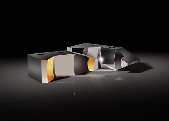
Manufacturing freeform optical surfaces and built-in alignment features in the same process improves manufacturing accuracy and ease-of-use for end users. These alignment features are beneficial for measuring surfaces during fabrication and facilitate end-user alignment. Courtesy of Edmund Optics.
Freeform optical surfaces can be defined as surfaces with no axis of rotational invariance within or beyond the optical part. This type of surface contains three or more independent axes, and results in asymmetrical features. In simple terms, freeform optics are not limited to spheres, rotationally symmetric aspheres, and off-axis conics.
Freeform surfaces in optical systems afford engineers additional degrees of design freedom that may be used to reduce the size and/or weight of an optical system or improve its performance while maintaining a comparable footprint.
“If the system requires high-performance imaging and has aggressive size, weight, and power goals, then the project is a good candidate for a freeform optical system,” said Joseph Spilman, president of Optimax Systems.
A freeform can not only replace some of the optical elements needed in an optical assembly but also enable optical systems to become stealthier by conforming to a particular shape being used, such as in conformal optics.
“We are seeing applications especially for military, aerospace, head-up displays, AR/VR systems, and astronomy,” said Rob Bechtold, vice president at OptiPro Systems.
In recent years, many commercially available optical manufacturing and metrology platforms have released freeform modules that are capable of grinding, polishing, and measuring these complex optical components.
In most cases, interest grew from the development or use of aspheric lenses. As advancements were made toward more challenging surface geometries, freeform optics became the natural evolutionary choice.
Jannick Rolland, director at the Center for Freeform Optics and CTO and cofounder of LighTopTech, was working on augmented reality displays in 2006 when she first speculated that more complex surface shapes might help to overcome the numerous trade-offs in design and the limited ability to correct optical aberrations using conventional optics.
This led Rolland to explore the possible solutions posed by “more complex shapes,” as she initially dubbed them, and what became known today as freeform optics.
Rolland said she and her colleagues enlisted the help from one of the best optics manufacturers in the U.S. to fabricate their first freeforms in 2007. Despite this, their first attempt “had so many mid-spatial frequencies (MSFs) that it functioned partially as a diffraction grating, inducing significant rainbow effects from what was a mirror in principle.”
Today’s freeform optical surfaces are much improved. For example, diamond machining can reach surface roughness as low as 1 nm and surface accuracy in the order of 20 nm. These tools, as well as precision glass molding, are now enabling more optics manufacturing companies to enter the freeform optics space.
Concurrent engineering
During the last decade, the industry has learned a lot about the optimal ways to design, determine tolerance, manufacture, test, and assemble freeforms. For example, understanding the requirements for manufacturing a freeform has reached a level in which datum surfaces and fiducials are being designed directly into the parts.
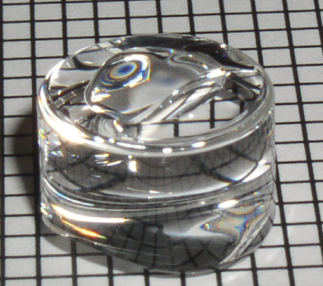
Different views of an automotive lidar glass lens. Courtesy of LightPath Technologies.
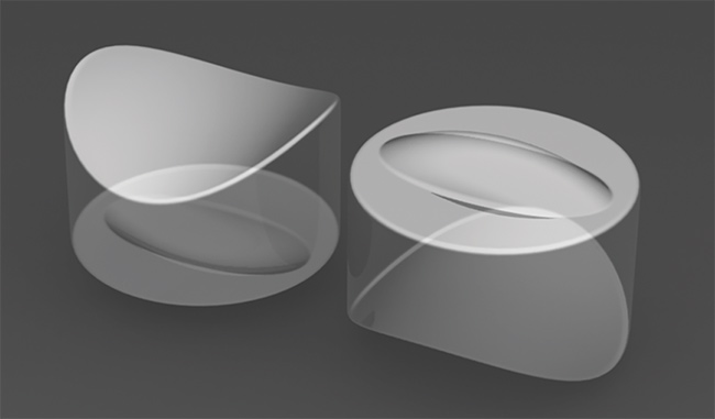
Solid model rendering of a beam-shaping optic. Courtesy of LightPath Technologies.
However, several critical points must be considered before manufacturing can physically begin. Unlike traditional optics, freeforms require more thought to be given to each stage in the process chain. Known as concurrent engineering, freeforms essentially need to be designed not sequentially, but in parallel with other critical aspects of system engineering to avoid expensive redesign cycles.
“Key aspects toward successfully making freeforms in a reasonable time are to first specify the clear aperture, extended aperture, datum, and fiducials to orient the part that may be used in metrology and assembly,” said Rolland.
The behavior that occurs outside the clear aperture can be particularly challenging in freeforms. Often, freeform surfaces have extreme shapes outside the clear aperture. To reduce unwanted edge features and uncertainty in measurement, it is helpful to extend the surface outside the clear aperture during manufacturing. If the curve suddenly changes direction and/or has an extremely steep slope, it is more challenging to manufacture.
At the top of the list for Bechtold is a clearly defined datum structure from which other features can be referenced. “A robust datum structure is the single most important feature needed for manufacturing freeforms,” he said. “If the datum structure isn’t properly defined or leaves room for interpretation, discussion with the customer will be necessary in order to mitigate any major geometry and/or program scope changes down the line.”
Although manufacturing freeform optical components poses some additional challenges compared with traditional optics, their very nature offers remarkable opportunities to compensate for, or at least reduce, many of the optical aberrations that are otherwise unavoidable.
Software considerations
The initial design phase of the freeform requires close communication between the designer, end user, and/or the manufacturer. At this point, opportunities and options can be discussed to make the part easier to grind, polish, measure, and align.
“Consider how the component will be held during both the manufacturing and measuring processes,” Bechtold said. “If this point is not considered up front, manufacturers will find themselves spending a lot of time aligning and realigning the components.”
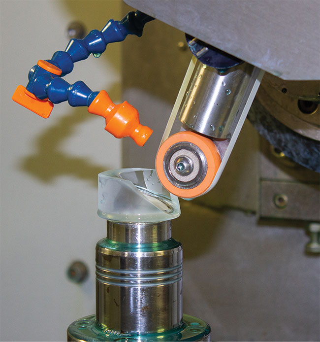
Sub-aperture polishing of a freeform optic. Courtesy of OptiPro.
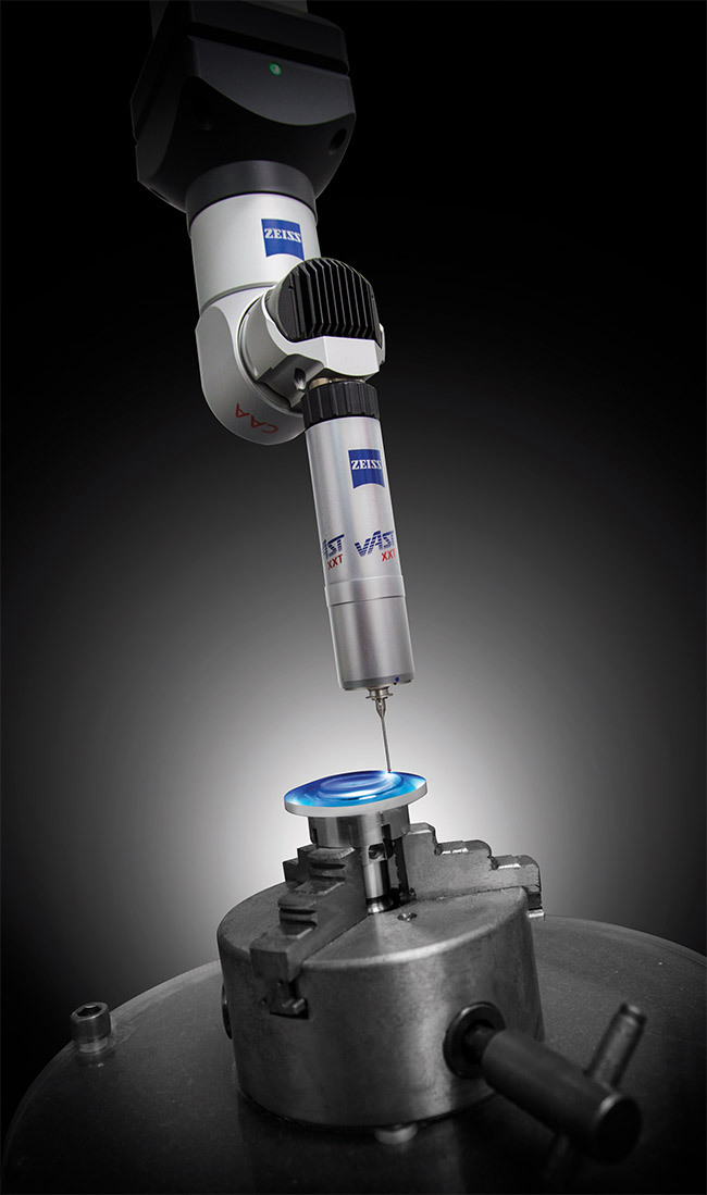
Measuring a freeform optic with noncontact metrology. Courtesy of OptiPro.
This is also the point to discuss the machines, software, and measuring systems needed to produce the part.
Freeform optics come in various geometries and sizes that can only be manufactured with sub- or mid-aperture-style tools during the grinding and polishing stages.
Grinding, polishing, and measuring all require software and hardware that is less frequently used in conventional manufacturing of precisions optics. For example, traditional computer-aided manufacturing software packages do not accomplish what is needed for deterministic grinding and sub-aperture polishing.
Companies such as OptiPro have developed their own computer-aided manufacturing software that, in OptiPro’s case, creates “dwell-based” deterministic tool paths for grinding, polishing, and measuring freeforms. Such software enables a technician to attack specific zones of error on a lens, to only remove material where and when it is necessary.
“This differs from more conventional methodologies because those will tend
to remove material from zones across the entire lens, not necessarily always
uniformly,” Bechtold said. “The largest impact of this is process speed and control: Controlling removal rates and amounts in optical manufacturing is
paramount, especially in freeforms.”
Manufacturers who can get the process chain exactly right can nail the shape the first time around without the need for advanced testing, Rolland said.
“Testing is important for quality control but not necessarily for a successful product,” she said. “If it does not perform, testing is required to debug the source of the error, which could be optical or mechanical.”
Subtractive manufacturing dominates
Today’s fabrication methods are dominated by subtractive manufacturing, which encompasses grinding, polishing, turning, and milling. Subtractive
manufacturing is used to directly
machine the freeform itself or to fabricate a template that can produce repeatable freeforms.
The most suitable approach — direct machining or molding — depends on the volume of production as well as the size, weight, and performance parameters of the freeform.
“The most common freeform end-use applications today tend to be either very high volume, which might favor molding
technologies to economically achieve the volumes for markets like AR/VR, or smaller volume uses like off-axis telescope systems for CubeSats that have much more stringent manufacturing specifications,” said Jessica DeGroote Nelson, senior director of strategic optical innovations at Edmund Optics.
While 3D printing of freeforms has future potential, it currently lacks the required accuracy for these optics. Another additive manufacturing technique, lithography, is a mature process poised to pave the way for future opportunities in metaform optics.
Metaform optics consist of a metasurface — otherwise known as a flat optic — written directly on a freeform substrate to create a single highly enabling optical component, according to Rolland, who first demonstrated the approach in a paper published in Science Advances in 20211. “To date, 3D printing offers a unique opportunity to print mirror substrates with support structures that are challenging, if not impossible, with subtractive methods,” DeGroote Nelson said. “However, although there has been significant progress, 3D-printed optics require post-polishing to achieve precision optical specifications.”
Ultra-precision direct machining
Using freeforms for imaging requires a level of precision in the order of nanometers. Since freeform surfaces lack an axis of rotational invariance, their fabrication requires more than the two degrees of freedom that is typically permitted using conventional manufacturing methods.
Ultra-precision machines use multiple geometric configurations with up to six degrees of freedom to move a rotating
diamond tool relative to an optical
surface. This process does not typically
require polishing. Polishing is an iterative-loop process that continues until the residual surface error and surface
finish reach a nanometer-level error.
“The challenge with freeforms is that sub-aperture removal typically introduces mid-spatial frequency errors, a type of surface artifact created by the small tool used to sculpt the surface,” Rolland said.
Further, sub-aperture removal techniques, such as turning, milling, grinding, and polishing of residual surface textures, all have signature characteristics of the fabrication processes and tool paths. Each additional degree of freedom adds error sources and increases the complexity of motion control.
Randomizing the tool’s path is one strategy to disrupt the surface errors’ structured nature. In the future, femto-
second laser polishing, among other laser-based techniques, could be used to achieve better than nanometer-level surface precision.
Some ultra-precision freeform
machines offer nanometer surface finishes (i.e., <10 nm peak-to-valley) with an angular resolution of 1.75 nrad. Freeforms of this quality have applications in remote sensing, such as within the hyperspectral imagers onboard down-looking CubeSats.
Molding for volume production
Fabricating molds for freeform optics elicits the same challenges as those encountered during the direct machining of freeforms. It requires support of more than three degrees of freedom, and consideration of in-process metrology, surface roughness, and MSF errors.
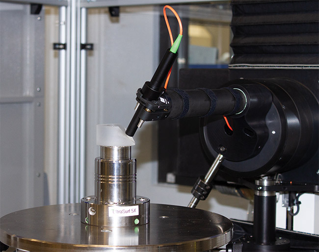
Freeform surfaces are so complex that interferometric metrology methods may not apply, and options may be limited to single-point coordinate measuring machines. This can increase uncertainty in the measurement and make it significantly more challenging to achieve a higher-precision surface. Courtesy of Edmund Optics.
However, once the mold is ground, polished (if needed), and validated for the desired results, it can be used for the repeatable fabrication of high volumes of cost-competitive freeform optics. Mold materials such as tungsten carbide or advanced ceramics are commonly used due to their chemical and thermal resistance.
For optical and infrared component maker LightPath Technologies, the manufacturing processes used for its current asphere molding were adapted to produce precision freeforms at a mass marketable cost and volume. This effort was recognized in January 2022 at Photonics West with a PRISM Award for Manufacturing presented by SPIE and Photonics Media.
“The glass freeforms we make are
advantageous for beam shaping and tighter directional control of light, which ultimately optimizes system performance,” said Mark Palvino, vice president of global sales at LightPath Technologies.
Mass-producible freeforms enhance consumer imaging applications such as AR/VR assemblies. In these applications, freeforms are central to producing smaller and lighter headsets that more closely resemble conventional eyeglasses than the cumbersome and bulky AR/VR goggles of today.
In addition, LightPath’s freeform optics enable lidar systems to achieve a larger field of view and reduce optical losses, which in turn translates to higher-resolution images and the ability to extend detection distances.
Precision glass molding addresses some of the limitations of plastic optics and it scales more efficiently for volume manufacturing. It also reduces the amount of costly and time-consuming grinding and polishing steps that are required for traditional direct machining.
Molded glass freeforms of up to 52 mm
can be manufactured with a surface roughness of <3 nm, peak-to-valley
surface error of <1000 nm, and surface error root mean square of <300 nm.
Metrology increases time and cost
Interferometry can provide form and MSF measurements on spherical surfaces and mild freeforms with an uncertainty of a few nanometers. But as a freeform surface becomes more complex, they may produce a fringe pattern that cannot be resolved by the interferometer’s camera and might thus require optical nulls or other techniques. For example, subaperture stitching can extend interferometric capabilities, enabling the measurement of optical parts with higher slopes. At this point, computer-generated holograms (CGHs) that produce reference wavefronts as optical nulls are a standard industry solution despite their limitations.
“Metrology can be challenging and time-consuming to test each lens in production volumes,” Palvino said. “It requires CGHs for each design, which are expensive and there are few supply options.”
White light interferometry is a null-free metrology approach that provides accurate measurements of surface roughness, MSFs, and even forms in some custom implementations. It can also routinely achieve sub-angstrom precision for surface roughness and MSFs2.
“The complexity of the design will impact the metrology method that can be used,” said DeGroote Nelson. “For example, if the surface is so complex, an interferometric method, such as CGHs or stitching interferometry, may not be possible and may be limited to single-point CMM [coordinate measuring machine].”
In this case, the uncertainty will be greater, and a higher precision surface will be significantly more challenging. This equates to higher cost.
“A designer may want to balance what is easier to measure in order to achieve a more precise wavefront correction,” DeGroote Nelson said. “For comparable spheres to aspheres, a ballpark cost estimate has always been two to three times.”
A similar comparison for manufacturing freeforms can be 5, 7, or even up to 20× more costly than a spherical optic of a similar size, depending on the degree of difficulty and the time required. This makes the design for manufacture critically important to lower the cost and achieve the required specifications.
Affordability is always a critical
parameter that will influence the optic and manufacturing method of choice, but as freeform manufacturing becomes more mainstream and more widely adopted, there will be inevitable economies of scale that result in cost benefits.
Future of freeforms
Increasing in popularity are monolithic freeforms, which combine multiple optical elements into a single form to reduce the number of elements, and therefore the size, of the optical system.
Edmund Optics was granted a patent on alignment features for monolithic freeform elements to aid in creating global coordinate systems to manufacture and test the surfaces in their monolithic (pre-aligned) state. A useful advantage of this approach is the diamond turning of both optical surfaces and datums for alignment or mounting, which can be manufactured at the same time in a patented process. This improves the process accuracy and ease-of-use for end users.
“Diamond turned optics typically need to be taken off and put back between each of the multiple diamond turning steps needed to create different optical surfaces and alignment/mounting datums, and process accuracy is reduced each time this happens,” DeGroote Nelson said. “However, this manufacturing method involving restraining the monolithic optic to a machining fixture allows for multiple features to be diamond turned without removing the part, significantly improving process accuracy.”
References
1. D. Nikolov et al. (2021). Metaform optics: bridging nanophotonics and freeform optics. Sci Adv, Vol. 7, No. 18.
2. J. Rolland et al. (2021). Freeform optics for imaging. Optica, Vol. 8, No. 2, pp. 161-176.