Photonics HandbookTest & Measurement
Optical Delay Lines: Key to Time-Resolved Measurements
To obtain an accurate means of creating reliable delays in any time-resolved spectroscopy or dynamic experiment, several factors about the delay line stage must be considered to reduce or eliminate errors associated with linear stages.
MKS/Newport
One of the most critical elements of any time-resolved spectroscopy and dynamics experiment is the optical delay line. A typical optical delay line consists of a retroreflector or folding mirrors on a translation stage (Figure 1). When selecting the translation stage, certain parameters from the stage and the driver or controller should be taken into account, as they affect data analysis and interpretation. Key motion-control parameters that affect the time-resolved measurements include total delay, minimum incremental motion (MIM), repeatability, accuracy, and mechanical errors.
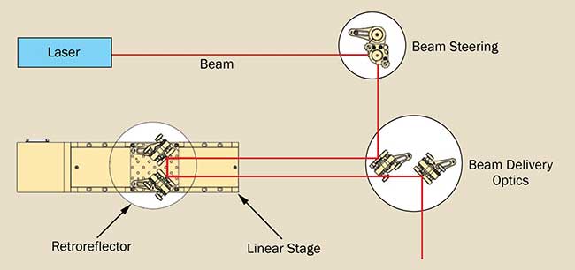
Figure 1. General schematic of the optical delay line.
The first parameter to consider for the linear stage is the total delay (T) — the time it takes for the light to travel to the retroreflecting optics and make a return path. This is directly related to the travel range of the linear stage (L): T = 2*L/c, where
c is the speed of light in vacuum. The next most important parameter is the delay resolution (Δτ), which is related to the MIM of the translation stage and is calculated as Δτ = 2*MIM/c.
It is important to distinguish between the MIM and the resolution of the motion system, as they represent two different concepts. MIM is the minimum incremental motion that a device is capable of consistently and reliably delivering, and it is therefore a system capability; the resolution (display or encoder resolution), on the other hand, is the smallest controller display value or smallest encoder increment and refers to a design feature.
High repeatability
Another stage parameter as important as MIM is the stage repeatability, which refers to the ability of a system to achieve a commanded position over many attempts (Figure 2). In a typical time-resolved measurement, the linear stage is scanned over a certain distance (which corresponds to specific time delay), and some signal from the target sample is recorded as a function of time delay. Depending on the signal strength from the sample and the expected signal-to-noise ratio, the average of many scans is a method that has been routinely employed in time-resolved measurements. With this procedure, it is critical that the linear stage has high repeatability. Depending on the scan type (forward or cycle), repeatability (unidirectional or bidirectional, both forward and back) becomes an important factor.
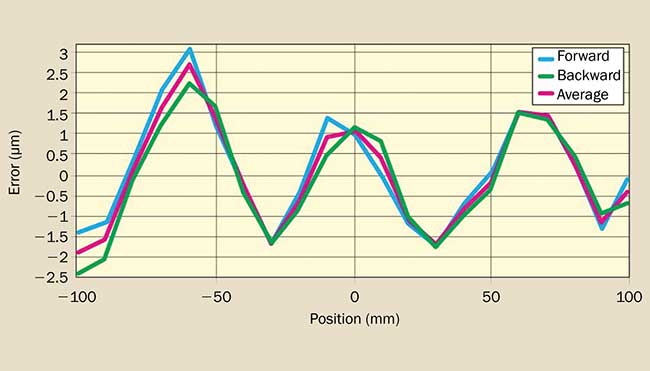
Figure 2. Repeatability of a typical linear stage.
Runout of linear stage (both linear and angular runout) can affect the position accuracy, so it is another important factor for selecting the right motion system for delay-line applications. Flatness and straightness (linear runout) represent the deviation from the ideal straight-line motion, and these are perpendicular to the direction of the travel in horizontal and vertical planes, respectively. Pitch and yaw are rotations around the axis perpendicular to linear motion (perpendicular to the direction of travel) in the horizontal and vertical planes, respectively (Figure 3a). Roll is the rotation around an axis in the direction of travel.
The magnification of the angular errors over distance (Abbe error) is shown in Figure 3b. In the simplest variant of time-resolved measurements (the pump-probe scheme), the pump and probe beams are spatially overlapped at the target sample, and the temporal overlap is altered by scanning the linear stage. Runout of the stage (especially angular runout) is an important factor, as it is an indication of how the spatial overlap is preserved during the scan of temporal overlap. The pitch and yaw become even more critical in configurations where the target sample at which the beam should be spatially overlapped is far from the delay stage (Figure 3c).
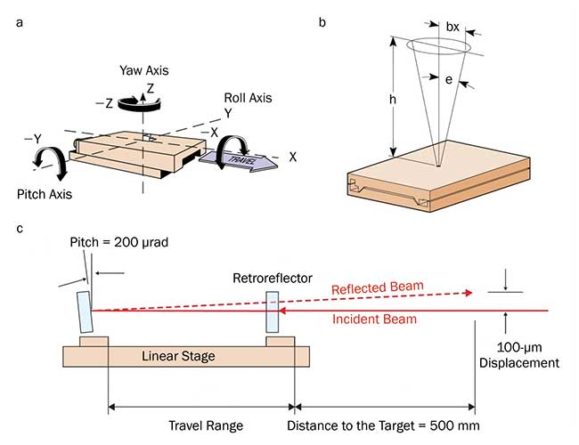
Figure 3. Illustration of pitch, yaw and roll (a), Abbe error (b) and the effect of linear stage pitch
on the overlap of two beams in a pump-probe experiment (c).
Translation-stage accuracy
In the time-domain version of multidimensional spectroscopy — i.e., 2D spectroscopy — where time-domain signals are Fourier transformed to get the frequency domain axes, more than one translation stage is required to get the frequency in two axes. In either electronic or vibrational 2D spectroscopy, the pulse sequence consists of three pulses and a local oscillator to recover the phase of the emitted signal in the phase-matched direction. The time accuracy of the pulse sequences is of paramount importance, because it results in a decrease of the detected signal strength and a distortion of the line shape (producing a ghost shape). The important stage parameter for this type of application is the accuracy of the stage.
The accuracy of the translation stage is the degree to which the commanded position matches the real position. In large part, this accuracy depends on the drive mechanism (leadscrew, ball screw, belt drive, or linear motor) and the feedback. Leadscrew- and ball-screw-based drives provide moderately good MIM but suffer from low accuracy, because they are used mainly in an open-loop configuration where there is no position feedback. In cases where there is position feedback, a rotary encoder at the end of the motor is typically used.
In addition, thermal expansion errors caused either by ambient temperature changes or the heat induced from the nut friction can reduce the accuracy of the stage. A linear motor-based system, in contrast to a screw-driven system, does not introduce any backlash because the linear bearing is the only friction point. In addition, these systems use linear encoders (as opposed to rotary encoders with screw-driven stages), which minimize thermal expansion errors, as well as cumulative and periodic errors inherent in leadscrews and ball screws.
Apart from the drive mechanism, the location of the feedback device in relation to the motor directly affects the accuracy of the motion system. The closer the feedback device is to the object being controlled, the more effective it will be in achieving the desired position. A rotary encoder is typically directly attached to the leadscrew or ball screw, which eliminates errors from belt, gear, or coupling windup or backlash, but the final position output still depends on the accuracy of the leadscrew or ball screw. The linear encoder scale, on the other hand, is directly attached to the translation stage carriage, and the position of the carriage and mirror is read directly.
The linear or monotonically increasing errors include cosine error, inaccuracy of the leadscrew pitch and angular deviation at the measuring point (Abbe error), and thermal expansion effects can be offset by linear error compensation. Graphically, these errors can be approximated by the slope of a best-fit straight line on a plot of position versus deviation (Figure 4). Knowing the slope of this line (error/travel), one can estimate the accuracy after linear compensation error as: Accuracy (after linear compensation) = Accuracy (before linear compensation) — (Slope*Travel), where Slope is the slope of best fit to the aforementioned graph, and Travel is the travel range of the translation stage.
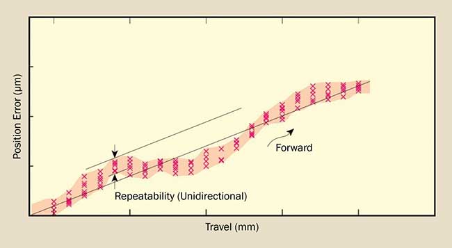
Figure 4. Estimation of on-axis accuracy after linear error compensation.
Nonlinear errors are compensated by error mapping using a laser interferometer. A typical laser interferometer is based on a Michelson interferometer consisting of a stable light source, polarization beamsplitting optics, a retroreflector on a translation stage, and a detection system. After reading the position (by the interferometer) at each increment, a text file representing the position and the associated error at that position is created. Depending on the level of position accuracy needed, different numbers of points are selected. This text file is then fed to the controller so it takes into account the positioning error correction when moving to the commanded positions. The final accuracy after error mapping can be as low as a few hundred nanometers for stages with linear encoders.
Images courtesy of Newport
/Buyers_Guide/MKS_Newport/c10218