To appease the demand for bandwidth, telecommunication operators are pushed to increase the per-channel data rate of wavelength division multiplexing (WDM) systems.
Steve Yao, General Photonics Corp.
As bit rates increase to meet expanding demand, systems have become increasingly sensitive to polarization-related impairments. These include polarization mode dispersion (PMD) in optical fibers, polarization-dependent loss (PDL) in passive optical components, polarization-dependent modulation (PDM) in electro-optic modulators, and polarization-dependent gain (PDG) in optical amplifiers.1
These impairments result from imperfections in the optical fibers. If the fibers were perfect, the state of polarization (SOP) of the signal would remain constant, and the polarization-related impairments could easily be eliminated. However, the SOP of light propagating in the standard communication fiber varies along the fiber because of the random birefringence induced by thermal stress, mechanical stress and irregularities of the fiber core. Generally, at the output end of the fiber, the light is elliptically polarized with varying degrees of ellipticity, and with the major elliptical axis at an arbitrary angle relative to some reference orientation. Worst of all, the induced birefringence changes with temperature, pressure, stress and other environmental variations, making polarization-related impairments unpredictable.
Because polarization-induced penalties are time dependent, mitigation of the polarization-related impairments must be dynamic and adaptive to random variations.
Dynamic polarization control
A dynamic polarization controller can convert any given polarization state to any desired polarization state. It is the single most important element of PMD compensation for overcoming these impairments. An ideal dynamic polarization controller should offer several important parameters as follows, in addition to low insertion loss and high return loss:
• High speed is essential for tracking fast polarization variations such as those caused by locomotives passing fibers laid along railway tracks or by ocean waves in undersea fiber trunks. In field measurements using a PMD transient recorder, fluctuations with a time scale of a few milliseconds have been observed. Therefore, the response time of the dynamic polarization controller for PMD mitigation must be less than 1 ms. In practice, a response time less than 100 µs is required.
• Activation loss measures the additional insertion loss caused in activating the device. It is defined as the difference of the maximum and minimum insertion losses of the device considering all possible activation conditions. This specification is particularly important because all the compensation schemes for polarization related impairments use feedback signals to activate the controller. The activation-induced loss or fluctuation causes errors in the feedback signal and directly degrades the performance of the compensation apparatus.
In addition, when an instrument for measuring the PDL of optical components includes a polarization controller, the activation-induced loss limits the resolution and accuracy of the measurement. Similarly, the controller’s PDL also contributes to errors in a feedback system and complicates the design of compensation hardware and software.
• Wide operation bandwidth is important for dense WDM (DWDM) systems that cover a broad wavelength bandwidth. Wide-bandwidth polarization controllers function equally well for many wavelength channels, simplifying system design, reducing system cost and enabling the expansion of system bandwidth.
• Uninterruptibility is also critical for dynamic polarization controllers in optical networks because any polarization reset may cause unacceptable signal outage.
Commercial polarization controllers fall into three technology classifications: multiple wave plates with fixed retardations but variable orientation angles; a single wave plate with both variable retardation and orientation; and multiple wave plates with fixed orientation and variable retardation.
Controllers based on wave plates of fixed retardation are wavelength-sensitive. Those that rely on physical rotation are generally slow. Other than these fundamental limitations, all three approaches function reasonably well in principle. However, implementation of these approaches in practice determines the performance, cost and reliability of the devices.
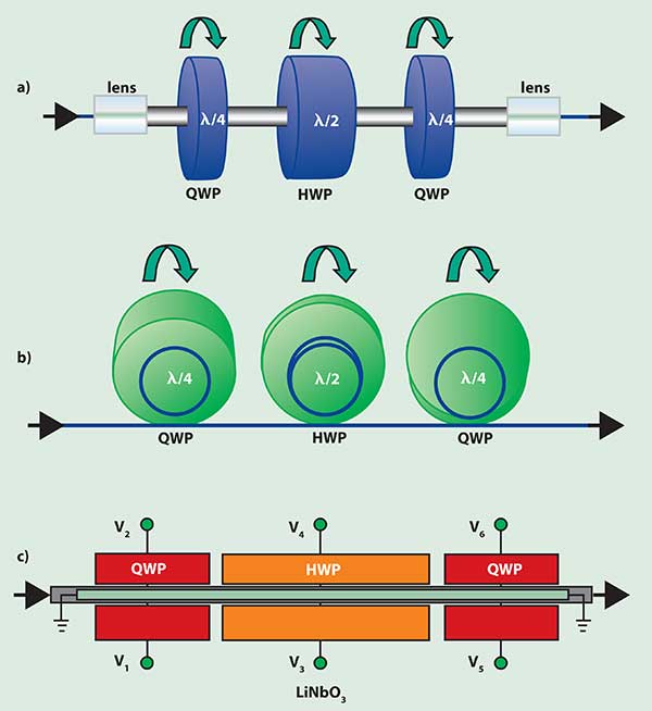
Figure 1. Polarization controllers that use multiple wave plates with fixed retardation and variable orientation angles tend to be slow and wavelength-sensitive; (a) the free-space optics approach, (b) the fiber coil (mickey mouse ears) approach, and (c) the electro-optic waveguide approach.
A classic polarization controller consisting of three rotatable wave plates is illustrated in Figure 1a. In this configuration, a half-wave plate (HWP) is sandwiched between two quarter-wave plates (QWP) and the retardation plates are free to rotate around the optical beam with respect to each other. The first QWP converts any arbitrary input polarization into a linear polarization. The HWP then rotates the linear polarization to a desired angle so that the second QWP can translate the linear polarization to any desired polarization state. In this approach, the retardation of the plates is fixed, but the relative angles of the retardation plates are variable.
Commercial applications of this approach have produced respectable results. However, this technique does have drawbacks: Collimating, aligning and refocusing are time consuming and labor intensive. Also, the wave plates and microlenses are expensive and need antireflection coating or angle polishing to prevent backreflection. Insertion loss is high because the optical beam has to be coupled out of one fiber and refocused into another. Furthermore, the wave plates are inherently wavelength-sensitive (any fractional wave plate is always specified with respect to a particular wavelength), making the device sensitive to wavelength variations. Finally, electrical motors or other mechanical devices rotate the wave plates, limiting the controller speed.
Unlimited options
An all-fiber controller based on this mechanism (Figure 1b) reduces the insertion loss and cost. In this device, three fiber coils replace the three free-space retardation plates. Coiling the fiber induces stress, producing birefringence inversely proportional to the square of the coils’ diameters. Adjusting the diameters and number of turns can create any desired fiber wave plate.
Despite the reduced loss and cost, the device still suffers from wavelength sensitivity and low speed. In addition, because bending the fiber generally induces insertion loss, the fiber coils must remain large and the resulting device is generally bulky. Therefore, the use of these mickey mouse ear controllers is primarily limited to laboratories.
For network deployment, speed is essential and physically rotating the wave plates cannot meet the need. For this reason, LiNbO3-based high-speed polarization controllers (Figure 1c) were developed. One such controller comprises three waveguide sections, two of which simulate a QWP, and one of which simulates an HWP. However, instead of rotating the wave plates, two voltages and the electro-optic effect determine the relative orientation (effective optical axis) of each. Proper voltage adjustments can achieve endless rotation of each wave plate. Examples of the control voltages for the three wave plates are illustrated below:
V1 = Vasinα – Vbcosα – Vc,
V2 = Vasinα + Vbcosα + Vc
V3 = Vdsinβ – Vecosβ – Vf,
V4 = Vdsinβ + Vecosβ + Vf
V5 = Vgsinγ – Vhcosγ – Vi,
V6 = Vgsinγ + Vhcosγ + Vi
where α, β and γ are three endlessly adjustable parameters that determine the orientations of their corresponding wave plates, and Va to Vi are nine predetermined voltage parameters.
Unfortunately, the price for this speed increase may not be acceptable for network applications. High insertion loss (~3 dB), high polarization-dependent loss (~0.2 dB), high activation loss (~0.15 dB) and high cost are the major disadvantages. The device also has at least nine parameters to optimize, making implementation complicated and costly.
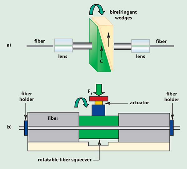
Figure 2. Polarization control with a single wave plate with variable retardation and orientation is slow but wavelength-insensitive; (a) a free-space optics approach, (b) an all-fiber approach with rotatable fiber squeezer.
In an alternative approach, a Babinet-Soleil compensator can convert any input polarization state into any desired output polarization state. The heart of such a device (Figure 2a) is a composite wave plate made from two birefringent crystal wedges. The thickness (and therefore the total retardation) of the wave plate varies by sliding the two wedges against one another. The orientation of the composite wave plate can also rotate around the optical beam.
Compared with the previous device (Figure 1a), this has the advantage of insensitivity to wavelength because precision retardation can be achieved for any wavelength. However, it suffers from high cost, high insertion loss and low speed.
To reduce the cost and insertion loss, an all-fiber polarization controller based on the Babinet-Soleil compensator principle was developed (Figure 3b) in 1996 with the trade name PolaRITE. The device comprises a fiber squeezer that rotates around the optical fiber. Applying a pressure to the fiber produces a linear birefringence, effectively creating a fiber wave plate whose retardation varies with the pressure. Simple squeeze-and-turn operations can generate any desired polarization state from any arbitrary input polarization.
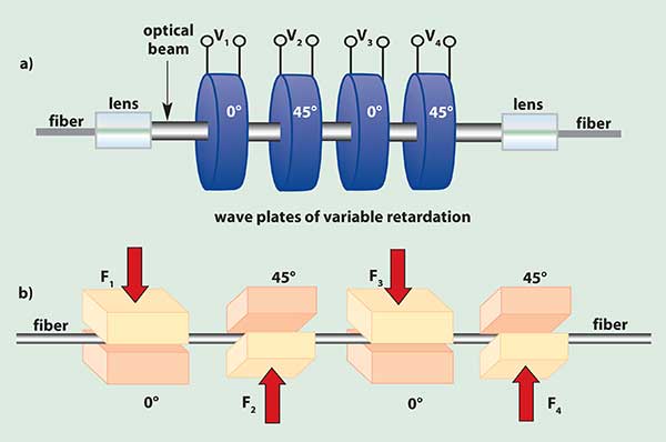
Figure 3. Multiple wave plates with fixed orientation and variable retardation
make dynamic polarization controllers that are fast and insensitive to
wavelength; (a) the free-space optics approach has voltage, insertion-loss, cost and bandwidth limitations, (b) an all-fiber squeeze solution is fast, reliable and low cost.
In addition to low insertion loss and low cost, the device is small and wavelength insensitive, especially compared with the mickey ear controllers. This makes it useful for integration into WDM modules. However, similar to the controllers that rely on physical rotation, this device is too slow to be used for dynamic PMD compensation in fiber optic networks.
Polarization controllers also can be made with multiple free-space wave plates oriented 45° from each other (Figure 3a). The retardation of each wave plate varies with an applied voltage; however, the orientation angles are fixed. These variable retardation wave plates can be made with liquid crystals, electro-optical crystals or electro-optical ceramics. The disadvantage of the liquid crystal device is low speed and the electro-optical one generally requires high operation voltages. Such a polarization controller generally has high insertion loss, high cost and limited bandwidth due to the antireflection coatings and the microlenses.
All-fiber solutions
An all-fiber device based on the same operation principle (Figure 3b) would reduce the insertion loss and cost. The retardation of each wave plate varies with the pressure of each fiber squeezer. The challenge is making the device reliable, compact and cost-effective.
In PolaRITE II2, a commercial dynamic polarization controller, piezoelectric actuators drive the fiber squeezers for high speed. Because it is an all-fiber device, it has no backreflection and has extremely low insertion loss and polarization-dependent loss. Its response time of 30 µs is fast enough to track the fastest polarization fluctuations in field-installed fiber links. With proper control procedures, endless (or reset-free) polarization control can be achieved without disruption.
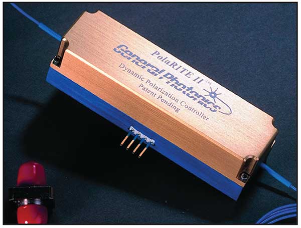
Figure 4. A fiber-squeezer-based dynamic polarization controller.
With an activation-induced loss of less than 0.003 dB, it is also useful in high-precision PDL instrumentation and in feedback loops for compensating polarization-induced penalties. It is also independent of wavelength, working equally well for signals ranging from 1280 nm to 1650 nm.
System applications
A fiber-squeezer-based dynamic polarization controller (DPC) offers low insertion loss, low PDL, low activation loss, low backreflection, high speed and low cost. It is ideal for optical system applications to overcome the polarization-induced impairments, as shown in Figure 5a-e. The applications where DPC can play a significant role include:
• PMD compensation: A typical first-order PMD compensator (Figure 5a) comprises a dynamic polarization controller followed by a fixed or variable differential-group-delay (DGD) element.3 The PMD along the link can be monitored through measuring the degree of polarization (DOP) by using an in-line polarimeter.2 The DOP information is then fed back to control the DPC and the DGD value of the compensator. The typical response time of the monitor and DPC is less than 100 µs.
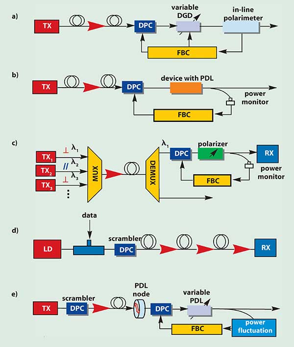
Figure 5. Communications systems with polarization-induced impairments need dynamic polarization controllers that are fast and have low losses: (a) polarization-mode-dispersion (PMD) compensation, (b) polarization optimization, (c) polarization-assisted crosstalk reduction (d) polarization-dependent-gain (PDG) mitigation, (e) polarization-dependent-loss (PDL) compensation. (DPC: dynamic polarization controller; FBC: feedback circuit.)
• Polarization optimization: Various optical components or modules in a transmission link, such as electro-optic (E-O) and electro-absorption (EA) modulators, optical interferometers and heterodyne optical receivers, are polarization sensitive. A dynamic polarization controller can be used in such a link to minimize the polarization sensitivity by optimizing the output power of the components or modules (Figure 5b). This scheme also can be used to reduce the effect of PDL in various passive components.
• Polarization-assisted crosstalk reduction: In order to increase the spectral efficiency of the DWDM systems, two polarization-related transmission techniques have been employed: polarization division multiplexing (PDM) where two channels have orthogonal polarizations at the same wavelength; and polarization interleaving where adjacent WDM channels have orthogonal polarizations.4 For the polarization interleaving scheme shown in Figure 5c, a dynamic polarization controller followed by a polarizer is used to reduce polarization-induced crosstalk between the adjacent wavelength channels.
• Polarization scrambling: The fiber-squeezer-based controller can also work as a polarization scrambler to effectively randomize polarization states. With a built-in resonant enhanced circuit, the half-wave voltages of the device at scrambling frequencies are reduced to only a few volts. With properly selected driving parameters, the scrambler has successfully achieved a minimum polarization sensitivity of less than 0.05 dB and a degree of polarization less than one percent. The main applications of polarization scrambling include:
1. PDG mitigation: The performance degradation due to polarization-dependent gain (PDG) induced in optical amplifiers in transmission systems can be suppressed by scrambling the SOP. The PDG magnitude is proportional to the DOP. A low DOP can reduce polarization hole burning (PHB) and suppress PDG (Figure 5d).5 DOP can be minimized by scrambling the SOP of the signal at frequencies that are higher than the inverse of the response time of the optical amplifiers (~milliseconds).
2. Polarization sensitivity elimination: The polarization scrambling can be used to eliminate an instrument’s polarization sensitivity. Some optical instruments, such as diffraction-grating-based optical spectrum analyzers, are sensitive to the SOP of the input light. Scrambling the input polarization can remove the measurement uncertainties caused by polarization sensitivity.
3. Facilitating PMD compensation: Polarization scrambling also can be used in systems to facilitate and simplify PMD compensation.6 For such an application, low residual phase modulation is essential. The fiber-squeezer-based polarization scrambler is especially suited for this application due to its lowest residual phase modulation.
• PDL characterization and compensation: Fast and accurate PDL characterization of fiber optic devices in a manufacturing environment is important. Fiber-squeezer-based dynamic controllers are especially attractive for this application because their low activation loss and low PDL greatly improve the PDL measurement accuracy. At a system level, in order to monitor and compensate the PDL along the transmission link, a fast polarization scrambler should be placed after the transmitter to monitor PDL value from the power fluctuation induced by PDL of the components or optical modules (e.g., EDFAs). The feedback signal controls the DPC and variable PDL source to minimize the power fluctuation (Figure 5e).7
In summary, a dynamic polarization controller based on fiber-squeezer technology is a key unit to overcome the polarization-related impairments for the optical network systems and to characterize polarization for instrumentations.
Acknowledgement
The author is grateful to the invaluable contributions by Lianshan Yan and James Shen of General Photonics Corp.
References
1. Yeh Chao et al. (October 2000). Overcoming polarization impairment. Fiberoptic Product News.
2. Application notes on PolaRITE, polarimeter, and variable DGD, General Photonics Corporation, 2000-2001. http://www.generalphotonics.com/.
3. Bulow H. (1982). PMD mitigation techniques and their effectiveness in installed fiber, Proc. OFC, ThH1.
4. Nelson L.E. Nielsen T.N., and Kogenlnik H. (2001). Observation of PMD-induced coherent crosstalk in polarization-multiplexed transmission. IEEE Photonics Technol. Lett., vol.13.
5. Lichtman E. (1995). Limitations imposed by polarization-dependent gain and loss on all-optical ultralong communication systems. J. of Lightwave Technol., vol. 13.
6. Rosenfeldt H. et al. (2001). Automatic PMD compensation at 40 Gbit/s and 80 Gbit/s using a 3-Dimensional DOP evaluation for feedback. Proc. OFC, paper PD27.
7. Yan L.-S., Yu Q., and Willner A.E. (2001). Demonstration of in-line monitoring and dynamic broadband compensation of polarization dependent loss. Proc. ECOC.