Optimizing the power and repetition rate of pulsed solid-state lasers allows materials processing at high resolution and high speed, a condition made possible by advances in intracavity harmonic generation.
Kenneth Ibbs and Alex Laymon, DPSS Lasers, Inc.
Many linear materials proceseqsing applications call for lasers with continuous-wave (CW) output. For example, early stereolithography systems were based on CW lasers such as argon-ion or HeCd. To use a pulsed, Q-switched diode-pumped solid-state laser in this type of application, the laser’s repetition rate must be such that the output appears to be continuous on the timescale of the process being performed — the so-called quasi-CW regime.
Noise effects cause traditional high repetition rate solid-state lasers to lose pulse energy and pulse-to-pulse energy stability as repetition rates increase to the quasi-CW level. This limits stereolithography systems’ process speed and resolution.
For many stereolithography systems, the trade-off between resolution and maximum draw speed (250 µm at 2.5-m/s system specifications) barely enables the solid-state lasers to meet the minimum criterion for geometrical continuity. At higher resolution, the quasi-CW criterion becomes even harder to achieve. Meanwhile, stereolithography customers are demanding tighter tolerances, smaller features and faster process speeds.
Advances in intracavity harmonic generation result in high-power, high repetition rate lasers in which noise is not related to repetition rate. These lasers can be used for high-performance stereolithography system upgrades that produce quality parts at both high speed and high resolution.
In some linear processes such as stereolithography, processing speed is determined by the interaction between the laser and substrate, which is in turn a function of the laser power. Hence, many OEM system builders have aimed to increase process speed by optimizing laser power. However, other laser characteristics may limit process speed, particularly when pulsed lasers operate in the quasi-CW regime. Many OEMs are using this regime because of the relatively low cost and high efficiency of high repetition rate Q-switched solid-state lasers compared with older CW gas lasers such as argon-ions.
The transition from CW to quasi-CW regimes is more complex than simply ensuring that laser pulses overlap by 50 percent or so at the process surface. In almost every case, the repetition rate/overlap required to achieve quasi-CW behavior is greater than initial estimates would suggest. This is often not the case in current laser processing systems, which compromise some specification — usually the minimum feature size — even though the laser’s repetition rate appears to be high enough to provide continuous processing.
Overlapping pulses
To ensure that a pulsed laser achieves quasi-CW operation, the temporal separation between pulses must be smaller than the dwell time of the focal region in which material is being processed. Pulse overlaps of 50 percent or more ensure a near-linear exposure with the “soft” edges associated with Gaussian beams. To maintain a 50 percent overlap, the geometrical maximum draw speed (SMax) of a system is given by:

where R is the laser repetition rate and D is the focus spot diameter.
This assumes that the laser’s pulse energy is at least the process exposure threshold, so one pulse within the focus area completes the process. If the pulse energy is below the exposure threshold, each focus position needs multiple (n) pulses: SMax = R × D/2n. (Note that this geometrical maximum draw speed does not ensure that the process parameters are close to those of the true CW regime.)
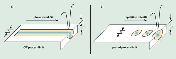
For a fixed average laser power, the relative process speed is determined by the volume interaction per second between laser and substrate. In either true CW or true pulsed regimes, it is straightforward to express the overall process speed in terms of the beam focus diameter (D) at the work surface, depth of penetration (d), and either system draw speed (S) or pulse repetition rate (R) of the laser.
In the true CW case (Figure 1a), the relative process speed is given by D × d × S. For a constant laser power, the draw speed varies as 1/D. For example, to maintain overall process speed but improve the smallest feature size by focusing the laser to one-half of the original diameter, increase the maximum linear draw speed by a factor of two.

Figure 1. Maintaining process speed while increasing resolution by a factor of two requires that the draw speed increase by a factor of two for either continuous-wave or pulsed operation. However, for pulsed operation, the laser repetition rate also must rise — by a factor of four, and with no loss of power.
In the true pulsed regime (Figure 1b), the process speed is given by the single pulse process volume [π (D/2)2 × d] times the laser repetition rate (R). In this case, the repetition rate varies inversely with the square of the beam diameter. As in the true CW case, maintaining process speed with a feature size half of the original requires that the geometrical maximum draw speed rise by a factor of two. However, to keep up, the repetition rate must increase by a factor of four — with no loss of power. Typically, the maximum repetition rate at which the laser’s power remains stable sets the limit of a stereolithography system’s effective maximum resolution.

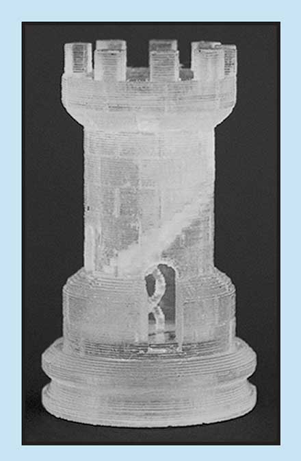
Figure 2. Pulsed solid-state lasers can process materials at high resolution and high speeds if their power and repetition rate are optimized for the application. A 50-mW diode-pumped solid-state laser operating at 30 kHz replaced the typical HeCd laser in a 3D Systems' SLA-250 HR stereolithography system to create this chess piece from RPC-100 ND resin. To achieve the smallest feature dimensions, the beam was focused to a 4.5-mil (115 μm) waist at the resin surface, and the layer thickness is 2 mil (50 μm). No postprocess surface finishing was necessary.
At sufficiently high repetition rates, the pulsed regime converges on the CW regime, becoming quasi-CW. The convergence level depends on the interaction between the laser and substrate. To identify the minimum repetition rate for quasi-CW processing, we increase the laser’s repetition rate until the process yields parts that are indistinguishable from those of a true CW source with the same resolution. We cannot meet this condition if the system noise increases (and thus power drops) rapidly with repetition rate.

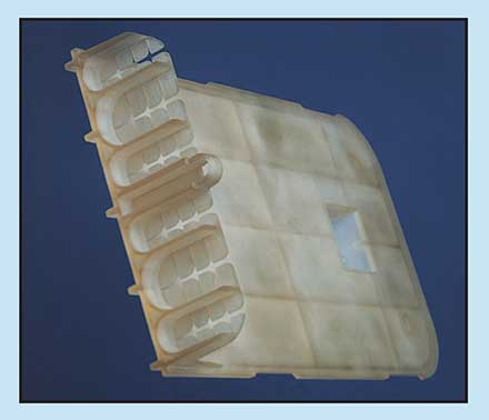
Figure 3. A 500-mW diode-pumped solid-state laser operating at 100 kHz replaced the typical CW argon-ion laser in a 3D Systems' SLA-500 stereolithography system to create this part from Somos 7120 resin. The beam waist was set at 10 mil (200 μm) and the layer thickness to 6 mil (150 μm).
For example, the SLA-500 system from 3D Systems of Valencia, Calif., operates at an order of magnitude higher power and half the resolution of the company’s SLA-250 HR. Judging from the simple geometrical continuity criteria in Equation 1, the data from an SLA-250 HR application (Figure 2) suggest that the repetition rate required for the SLA-500 would be about 30 kHz ×10 (power) × 0.5 (resolution) = 150 kHz, which is higher than commercially available diode-pumped solid-state lasers. In fact, because the repetition rate varies as the square of the resolution, the actual rate required to achieve quasi-CW behavior is only about 75 kHz at 500 mW, which can be achieved with commercial systems (Figure 3).
The trick, then, is to produce stable pulses at high repetition rates while generating harmonics from diode-pumped solid-state lasers.
Reduce noise
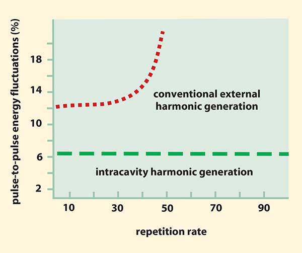
Generating laser harmonics is a nonlinear process, which exacerbates noise from the fundamental wavelength. In the case of multiple-harmonic generation, the final noise can be an order of magnitude greater than that of the fundamental. For conventional UV high repetition rate Q-switched solid-state systems with extracavity harmonic conversion, the increase in fundamental noise with repetition rate leads to a very rapid rise in pulse-to-pulse energy fluctuations (Figure 4). This limits the maximum repetition rate at which they can operate usefully. Efforts to reduce this noise have focused on reducing it at the fundamental.
The noise characteristics of quasi-CW lasers depend on the application and whether the laser is truly operating in quasi-CW regime. In the pulsed regime, noise is typically characterized by pulse-to-pulse energy stability. An example of this is disc texturing, in which laser pulses form tiny bumps on high-density storage media to prevent stiction. Despite the high repetition rates, each laser pulse produces one bump. Because all the bumps must be identical, the process demands pulse-energy stability and long-term average power. Disc texturing typically uses the fundamental 1064-nm output of an Nd:YVO4 laser. Efforts to use either the second or third harmonic have produced mixed results because of the inherently higher noise/instability.

Figure 4. For solid-state lasers employing extracavity harmonic conversion, noise increases with repetition rate, setting an effective maximum useful repetition rate. Intracavity harmonic conversion mitigates or eliminates this limit.
In quasi-CW applications, including stereolithography, we can characterize laser noise by the root mean square noise — provided the laser repetition rate is adequate to ensure true quasi-CW behavior. However, many OEM systems do not meet this rigorous quasi-CW criterion, so pulse-to-pulse energy stability remains essential to maintain the process integrity.
A laser’s maximum fundamental power requires an output coupler that balances the need for optical feedback to the cavity against the requirement to couple out as much power as possible. Reducing output coupling maintains high intracavity power, but only a small fraction of the power exits the laser. Increasing output coupling reduces the intracavity power faster than the higher percentage exiting the laser. If the losses exceed the gain, power falls to zero.
The maximum fundamental output power that can be extracted from a homogeneously line-broadened system is expressed by:

where Ab is the beam area, Is is the saturation intensity, α0 is cavity losses and g0 is gain. The maximum power that can be extracted from a particular system is the extraction efficiency η, which determines the ideal transmission and reflection characteristics of the fixed output coupling optics. The noise associated with the system shows up as fluctuations in Pout,max.
An intracavity harmonic-generation laser does not use a fixed output coupler. During the early buildup of a Q-switched fundamental pulse, when there is no harmonic conversion loss, the nonlinear crystals in the cavity are very low loss elements. As the pulse builds, some of the fundamental converts to harmonics, which is equivalent to increasing the output coupling percentage. The fundamental intracavity power will increase until the losses from harmonic generation offset the gain. These conditions are exactly the output coupling losses that would optimize the fundamental output power if it were a normal laser, and they represent the optimum extraction efficiency.
Because harmonic generation is a parametric process, it behaves as an instantaneous feedback loop to stabilize the intracavity power (and therefore the harmonic output power) against perturbations (noise) that change the cavity gain/loss characteristics during the Q-switched pulse buildup. If the fundamental power builds too slowly — for example, because of excess noise losses — the nonlinear conversion process slows so that intracavity power can build up to the nominal normal level, resulting in higher nonlinear conversion. The harmonic output power of a laser with intracavity harmonic generation follows the same form as Equation 2. This demonstrates the equivalence between optimizing the output coupling percentage of a fundamental laser with the harmonic conversion efficiency of a laser using intracavity harmonic generation.
Although the gain and losses in a cavity vary with repetition rate and would normally require one output coupler for each repetition rate, the nonlinear output coupling associated with harmonic generation always maximizes the harmonic output at all repetition rates.