This second of two articles discusses the tools optical designers need to tailor their designs to the appropriate manufacturing process, optimizing the cost of component fabrication.
Jeremy Govier, Edmund Optics Inc.
With the understanding of aspheric lens manufacturing provided in part one of this article, designers have the tools to optimize their aspheres; the next step is to understand how to specify and tolerance the asphere so it can meet its application’s requirements. Every manufacturing process needs metrology, whether to aid in an iterative process such as magnetorheological finishing (MRF) or simply to ensure the part meets its design requirements.
Testing accurately is not a simple endeavor. In the past, metrology limitations have affected asphere production capabilities as much as fabrication limitations. Asphere metrology technology has made great advances in the last decade in the form of new options, increased flexibility of surfaces that can be tested, and improved measurement accuracy, time and cost.
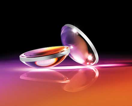
Best Form aspheric lens. Courtesy of Edmund Optics.
To review from the first article, aspheres can be manufactured with a variety of fabrication methods. Three subtractive methods polish the optics with small-surface-area tools: computer numerically controlled (CNC) grinding and polishing process uses precisely controlled tools, MRF uses a ribbon of magnetically responsive fluid to polish the surface, and diamond turning uses even smaller single-point tools to shape the optical surface.
Molding methods produce surfaces without removing material. Both precision glass molding and plastic injection molding can be used to produce aspheres. Precision glass molding heats glass to its softening point and compresses it between two molds; plastic injection molding forces liquid plastic into a mold then cools it to a solid.
No matter which manufacturing method is used, proper metrology to the necessary accuracy will ensure the parts meet required surface accuracies. This is even more important when using an iterative process such as MRF, which requires accurate surface data to adjust removal. Molding processes require less frequent metrology; however, it is still necessary to validate the production and ensure continued performance as tools wear down and are corrected.
The most common measurement techniques fall into two categories: interferometry and profilometry. Interferometry measures the difference of a reference wavefront and the wavefront either reflected off a surface or transmitted through the optic. Profilometry measures the changes in height of a part under test by moving a probe across the part; typically this is done in slices or spirals across the surface to build either a cross section or surface map of the surface heights. Profilometry tends to be simpler to set up and more flexible in the shapes it can measure but also tends to be less accurate. Using slices is generally faster but does not provide full surface information and can miss non-rotationally symmetric errors.
Interferometers measure wavefront deviation of a test wavefront from a reference. The reference can be as simple as a plane wave. A spherical reference is also very simple and common to achieve. The exact aspheric wavefront of the designed surface can be much more difficult to achieve and generally limits where an interferometer can be used for testing aspheres.
For very slight departures from a sphere, a typical spherical reference wavefront can be used, as long as the departures are within the dynamic range of the interferometer. Various types of stitching interferometers capitalize upon the fact that over a small enough aperture, the aspheric surface under test is close enough to a reference sphere to be within the measurement range, and then many smaller apertures can be stitched into a full aperture interferogram. All types of stitching interferometers have limitations on the shapes they can test based on slopes, rate of change of the radius and inflection points in the surface.
Null interferometry can also be used to generate a specific aspheric wavefront. This is done in two ways: null lenses or computer generated holograms (CGHs). A null lens is a specially designed and assembled spherical lens or assembly of spherical lenses designed to generate a specific, aspheric transmitted wavefront. A CGH uses holography to generate the desired wavefront when the specially designed plate is placed in the reference path of the interferometer. Both cases require specifically developed tools, and careful alignment and placement of the reference to achieve the desired wavefront.
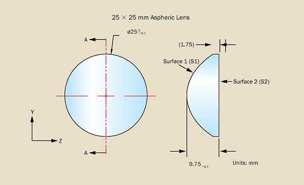
Typical aspheric lens print showing the coordinate system’s cross-section view and profile view. Photo courtesy of Edmund Optics.
Though null interferometry can be both expensive and time consuming to set up, once set up, it can rapidly test many identical aspheric surfaces. Compared with null interferometry, stitching interferometry can add more flexibility without special setup and tooling, though it is limited in what surfaces it can test. Profilometry is much more flexible but is limited in its accuracy.
The chosen metrology option will affect what accuracies can be achieved, what shapes can be manufactured, and both the setup and per-piece costs of the aspheres. If MRF is used for manufacturing to achieve very tight form errors, generally interferometry of some sort is needed to accurately collect full aperture-surface information. If looser form-error tolerances are acceptable, profilometry is the much more flexible option requiring less set up.
Accuracy of the surface
Most metrology for aspheres is for inspecting surface accuracies or measuring deviations from design in a finished asphere. These types of error come in many forms, and it is important to know what affects a specific application and how much error is tolerable. This will help specify only what is required and not add unnecessary costs to the part.
Surface accuracies are grouped into three types, based on their frequency across the surface of a part or the width of an individual deviation. Form errors are low-frequency or larger errors typically peaking one to three times across a slice of the part. Waviness (also referred to as midspatial frequency error) occurs three to 15 times across a part and is related to the size of the tool used to polish. Surface roughness is the high-frequency smoothness of a surface and is related to surface polish. The definition of the groups of surface errors is not rigid, and there can be overlap between what someone considers one group or another.
Form errors are usually the most important and commonly specified surface specification for aspheres. These call outs are very similar to those used for spherical optics. Form errors can be further fragmented by calling out the power or variation of the radius term. Irregularity refers to all other errors minus the radius variation and can further be broken out into rotationally and non-rotationally symmetric errors. Each of these distinctions can have very different effects on optical applications, and the sensitivity to them can be very different.
Radius error typically has much less effect on most applications than irregularities do. Small amounts of radius change can often be tolerated because they cause only small changes in focus. If radius is allowed to vary to a looser specification than other form errors, the optic can be manufactured less expensively. In general, it is advisable to allow for a looser radius tolerance, as this often will have a significant impact on manufacturing yields and costs. Radius tolerance can be specified directly as an allowable percentage change in radius or it can be specified as a power tolerance, which is a measurement of sagitta change caused by the change in radius. Generally the linear measurement of radius is preferable for an asphere but can either be used or converted to suit the measurement equipment.
Compared with irregularities, radius errors tend not to be as detrimental to performance. Non-rotationally symmetric errors are more detrimental than rotationally symmetric errors for most applications, making it possible to specify the two separately. Specifying a looser rotational symmetric irregularity than a non-rotationally symmetric irregularity typically will not have a noticeable impact on cost, so use only as necessary.
Irregularity is specified as a deviation from the ideal surface in microns or waves. It can be expressed as peak-to-valley (pv) or a root-mean-square deviation. Root mean square is often more closely connected to optical performance than pv errors, but again, this can vary with the application. Use the method that most closely matches what is modeled in the design analysis.
When a surface is polished with small polishing tools, as in CNC and MRF polishing, waviness may be introduced — but it is seldom present in conventional, whole-aperture polishing performed in spherical optics. As a result, waviness may need to be specified and controlled in an asphere while it is typically ignored in spherical lenses. The sensitivity to waviness is application-specific, and many lenses are not sensitive to it. Special testing, or at least special analysis of test data, is required to measure waviness, so it should be specified only if necessary.
Waviness can be specified as a slope error or a maximum deviation within a specified frequency range. It is important to spell out the frequencies when specifying waviness so there is a distinction from high-frequency noise. Depending on the resolution of test equipment, higher-frequency deviations might naturally be filtered from the test data because they fall within the resolution of the test.
Surface roughness is a measure of the quality of the polish on a surface. For some applications, this is important and necessary to control scatter and improve the laser damage threshold. Analyzing surface roughness requires very specialized testing such as white light interferometry, which can be a time-consuming process. It is best to call this out only as necessary, given the added testing costs.
Defining parameters on the print
To ensure an asphere is manufactured to meet its application’s requirements, it is important for the print to clearly define all important parameters of the lens.
For standards, ISO 10110 works very well for defining an aspheric surface. The newest version of the standard allows for very clear ways of defining the surfaces. However, the vast majority of prints don’t fully conform to any actual standard. No matter what standard is chosen, it is important to include the necessary detail and be clear with requirements. The first things to consider are the aspheric equation and coefficients used.
There are many options for equations to define the surface. Designers should explicitly state to manufacturers which equation is being used and, ideally, include the equation used on the print. It is advantageous to have the print define the shape with an equation the manufacturing and testing equipment can accommodate, though there are many options for equivalent definitions of the same shape. Even if the design is optimized with one equation it can often be expressed with another equivalent equation; an example where this is useful is when optimizing with Q-type polynomials.
There are numerous advantages to using Q-type polynomial equations when optimizing a design, including controlling the shape, which can help avoid manufacturing limitations. Unfortunately not all manufacturing and test equipment has adapted to inputting these equations directly. While the manufacturer can usually make the necessary conversion themselves, by not doing it first on the print, there is a risk of incorrect conversion or invalid assumptions. It is advisable to perform any conversion at the print stage so that it can be thoroughly checked first. Most manufacturing and test equipment can handle the even aspheric equation with no issue, so it is a very safe equation to go with when defining the shape on the print. Popular lens-design codes even have tools to convert from Q-type to even asphere, to make things simple.
Along with the equation used, it is important to clearly state the coefficients using the same terms as the equation.
Including a coordinate system to show the direction of positive and negative values from the equation is also extremely helpful.
A simple table giving some data points of surface sagitta is recommended as an error check when entering the coefficients.
The large number of digits used to describe an asphere can open up a lot of possibilities of transpositions and typos, so it is very useful to have a way to check that everything is entered correctly. This can also help eliminate confusion about the use of signs in the equation. A lot of data points are not necessary, just enough to catch errors in data entry.
The tolerance on the surface accuracy is necessary. As mentioned above, there are several ways to call out the surface accuracy, and it is necessary to clearly state what is needed. The ISO standard covers much of this very well. If ISO isn’t used, however, an explicit description of the tolerances is important.
Stock optics can be customized by size, shape and edges, improving the surface figure or accuracy of the optical surface. Photo courtesy of ASI.
Making choices
Spherical optical surfaces have been manufactured for centuries. Although fabricating spherical optics requires a great deal of expertise and attention to detail, the fundamental processes are well-defined. Aspheric fabrication is not an immature technology but it is still seeing rapid innovation. New fabrication methods are being extended to an ever-expanding range of materials. Metrology methods are being refined and developed, and the methods of defining and prescribing aspheric surfaces are constantly evolving.
Knowledge of manufacturing and metrology methods will help you properly tolerance and specify your aspheric surfaces. The background given in this and the previous article provides you with a foundation from which to build your own component designs. Perhaps the most important piece of advice, though, is to select a fabrication partner that is both experienced and innovative, and will help you select or define the proper components to fit your needs. Look for suppliers with a wide range of stock aspheres and the ability to produce custom parts in the volumes you require. Then be certain your manufacturing partner has access to options for fabricating and measuring your components.