Engineering Staff, AMETEK Precitech, Inc.
Ultraprecision machining can be defined in general terms as the removal of material from a substrate utilizing a machine tool that operates at a resolution of 10 nm (0.4 μin.) or less. The machining process may take the form of single-point diamond turning or free-form machining.
Although single-point diamond turning has been around for more than fifty years, the most significant technological advances first appeared in the 1980s. Today, diamond machining is a well-established and affordable process for the fabrication of highly accurate optical components as well as mechanical components requiring microinch dimensional tolerances.
Free-form machining has also proved to be an effective manufacturing process. A free-form optical surface is one which is not symmetric about any axis. Multiaxis machining and metrology systems are required to manufacture these optical components in various materials. Figure 1 shows a commercially available single-point diamond turning and grinding machine. Such a machine provides a reliable and proven deterministic method for producing a wide variety of electro/optical components including thermal imaging and night-vision systems, reflective mirrors for CO2 and YAG laser applications, crystalline materials for UV and microlithography, electroless nickel lens mold inserts, plastic lenses, telecommunication components and alignment devices.
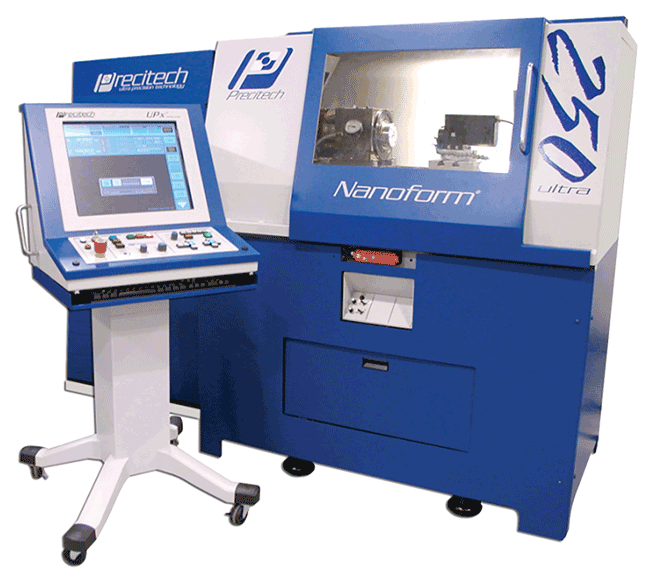
Figure 1. The Nanoform 250 ultra.
When combined with an ultraprecision vibration-free machine, a compact rigid tool holder and stable well-balanced fixture, a single-crystal natural diamond cutting tool will remove material from the substrates cleanly and efficiently. Because of the extreme level of sharpness on the diamond tool’s cutting edge, very small forces are generated during the machining process. The end result is a surface that exhibits optical qualities in both surface finish and form accuracy. In addition, single-crystal diamond cutting tools possess several other unique physical qualities that make them ideal for ultraprecision machining applications.
Minimal tool wear
When machining components to optical quality requirements, the slightest amount of tool wear can adversely affect the quality of the machined surface. Because of their extreme hardness and resistance to wear, diamond tools maintain their high cutting-edge quality throughout the machining cycle better than others. This results in highly reflective, low-scatter optical surfaces with figure accuracies on the order of 2 to 4 μin., peak-to-valley, as measured with a laser interferometer operating at 632.8 nm. Figure 2 shows figure and form of an electroless nickel-plated workpiece as single-point diamond machined on a commercially available device.
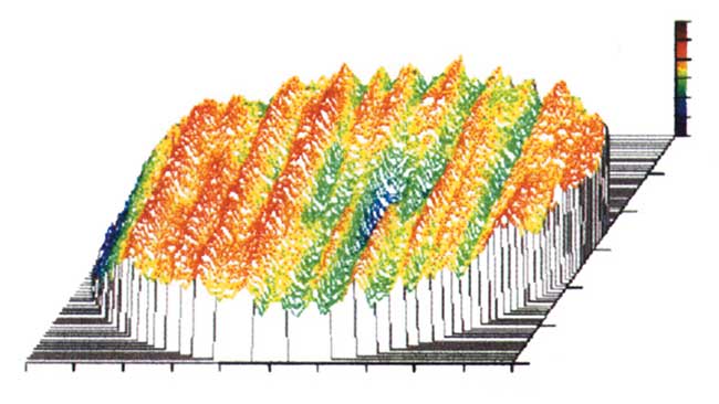
Figure 2. Results of diamond turning on an electroless nickel-plated workpiece.
Unlike carbide or CBN (cubic boron nitride) tools, which have random grain structures, single-crystal diamond tools have a very clear and well-defined grain structure. When mounting the tool in its shank, tool manufacturers orient the tool so as to make optimal use of the hardest point of the diamond. This is formed at the intersection of the top rake, which is generated in the 110-plane of the diamond, and the nose radius, which is generated in the 100-plane of the diamond. This orientation provides for the longest possible tool life, while also maximizing the tool’s resistance to wear. Because of the single-crystal grain structure,diamond tools can be sharpened to the level of atomic spacing, approximately 3 to 5 Å.
TABLE 1.
MATERIALS FOR MACHINING
| Metals |
|
Polymers |
| Aluminum Alloys (Al): |
|
Acrylic (PMMA) |
| 1100 |
|
Nylon
|
2011
|
|
Polycarbonate
|
| 2017 |
|
Polystyrene
|
2024
|
|
Polysulfone
|
5086
|
|
Acetal
|
5186
|
|
Fluoroplastic
|
6061
|
|
|
7051
|
|
Crystals
|
Copper (OFHC), (Cu)
|
|
Germanium (Ge)
|
Brass
|
|
Zinc Selenide (ZnSe)
|
Tin (Sn)
|
|
Zinc Sulfide (ZnS)
|
Silver (Ag)
|
|
Lithium Niobate (LiNb)
|
Gold (Au)
|
|
Cesium Iodide (Csl)
|
Nickel (Ni)
|
|
Potassium Dihydrogen Phosphate
|
(electroless &
|
|
Silicon (Si)
|
electrolytic plate)
|
|
Potassium Bromide (KBr)
|
Zinc (Zn)
|
|
Calcium Fluoride (CaF2)
|
Platinum (Pt)
|
|
AMTIR-1 |
Magnesium (Mg)
|
|
Neodymium:YAG (Nd:YAG)
|
Lead (Pb)
|
|
Indium Antimonide (InSb)
|
| Bronze |
|
Magnesium Fluoride (MgF2)
|
Proper orientation of the diamond in its shank, combined with precise grinding, lapping and polishing techniques, enables the cutting-edge radius to be accurately controlled. This means that the diamond tool’s form can be controlled to within microinch tolerances throughout the cutting arc (typically 100°) of the tool. Controlling edge waviness is extremely important when the ultimate in part-figure accuracy is required, since it reduces the possibility of errors being transmitted from the tool directly to the workpiece.
Because diamond has an extremely low coefficient of friction, chips created during the machining process have a natural tendency to slide across the top rake of the tool and away from the workpiece. This eliminates the buildup of chips at the tool’s cutting edge, thus minimizing scratching of the workpiece. Also, because of the particularly sharp cutting edge and low coefficient of friction, very little heat is generated during the process. The small amount of heat that is generated during the machining process is quickly drawn away from the workpiece because of the high thermal conductivity of the diamond tool. And because diamond has an extremely low coefficient of expansion, the tool remains very stable during the machining process. This means that the tool geometry remains constant, which is critical when attempting to achieve optimum quality optical surfaces.
Materials for machining
In most instances, many of the nonferrous metals lend themselves nicely to diamond machining. In addition, several polymers and crystals are also suitable. Table 1 shows materials that have been diamond machined at Precitech with various degrees of success.
There are several materials that cannot be machined using single-point diamond machining, the most obvious being ferrous metals and optical glass. The inability to machine ferrous metals with diamond cutting tools results from a chemical reaction in the presence of oxygen between the diamond and carbon. This chemical reaction causes graphitization, which rapidly destroys the cutting edge of the diamond tool.
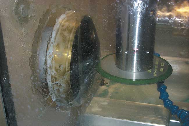
Figure 3. Ferrous or glass materials can receive complex geometric surfaces with existing machinery.
The inability to diamond machine glass results from a similar condition. The chemical reaction between the silicon content of the glass and the carbon content of the diamond creates silicon carbide, which also causes graphitization. With ferrous or glass materials, complex geometric surfaces are ground using existing machines (Figure 3). In-process aspheric form measurement devices allow the workpiece to be ground to form accuracies to λ/6 at 632.8 nm (Figure 4). Surface finish is then improved with postpolishing techniques to 4 to 8 Å (Figure 5).
Plating
If steel is required as a substrate, it is possible to plate with a thin layer of electroless or electrolytic nickel plating. Because electroless nickel plating is diamond machinable, the workpiece can be single-point diamond machined to the required optical accuracy. When using electroless plating, it is recommended that the plating be approximately 0.008 to 0.010 in. thick on all surfaces to be plated with a phosphorous content of 10 to 12 percent. The higher phosphorous content combined with proper heat treatment of the insert produces a surface with a Rockwell hardness of 50 Rc.
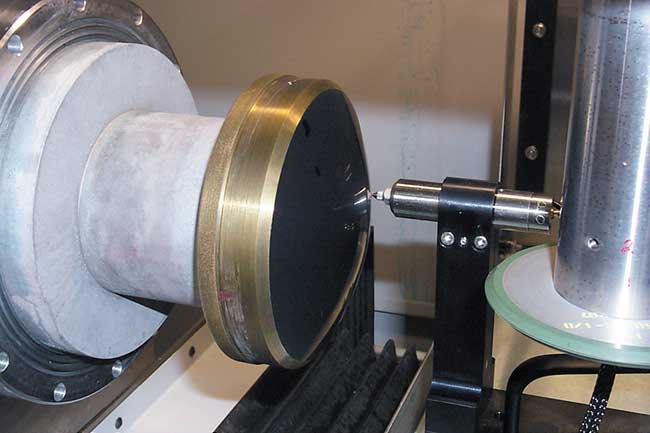
Figure 4. In-process aspheric form measurement devices provide high accuracies.
A typical application for electroless nickel-plated steel substrates is found in the mass production of plastic lenses for use in the ophthalmic and camera industries. Electroless nickel plating is applied to a rough machined stainless steel lens mold. The insert blank is then single-point diamond machined to its final requirements (Figure 6). This includes machining of the aspheric contour, as well as any surfaces required for alignment in the molding process. Applying additional nickel thickness allows for insert rework. The finished lens insert is then used in the injection molding process to replicate plastic lenses.
Free-form optics
Smaller, more competitive optical elements are driving the consumer electronic market. A major challenge in designing and fabricating optical components is the cost-effective manufacture of conformal or free-form components and their ultimate use in a wide variety of instruments and devices. A free-form optical surface is one which is not symmetric about any axis. Multiaxis machining and metrology systems are required to manufacture these demanding optical components.
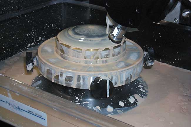
Figure 5. The surface is subsequently improved via postpolishing techniques.
Scanning mirrors for laser printers is one of the many applications utilizing glass or plastic elements to form a system. The original approach to solving this problem was to use a multiple of mirrors and elements to create a system. Free-form technology has allowed for component reduction by utilizing a series of aspheric mirrors and elements.
By replacing lenses in the optical system with a single free-form mirror, the number of components is reduced with the parallel benefits of size and cost reduction. Printing output is improved using the shorter wavelength laser, which results in a spot size reduction. Conversely, a long-wavelength laser can be used in a less expensive mass-production printer with the same free-form optical scanning system.
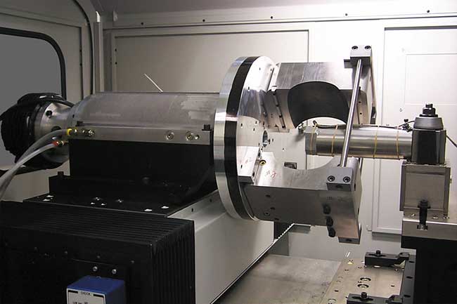
Figure 6. The blank is single-point diamond machined to its final requirements.
The design objective in utilizing a free-form mirror has resulted in a reduction in component size and an improvement in accuracy. A typical example is an existing component of 270 mm diameter being reduced to 110 mm and the accuracy of the element being improved from 0.4 to 0.15 μm or better.
This new class of optical component was fabricated using a multiaxis machine system designed specifically for manufacturing nonrotational, symmetric free-form optics. What is important is that a minimum of three axes of motion is provided. High-stiffness hydrostatic oil-bearing slideways combined with linear motors for driving the slideways are a key factor in providing smoother operation and better closed loop control of these axes.
Machine considerations
The most critical component to successful single-point diamond machining is the machine itself. The diamond turning machine must be free of both internal and external vibrations. The machine components, particularly the machine tool slides, must yield superior geometrical accuracies. Because of the extremely high level of accuracy required for optical components, any inaccuracies will be directly transferred to the workpiece. When utilizing a machine for ultraprecision machining applications, users should incorporate the following features into the machine.
The machine base must be well-supported in a fabricated steel frame. The base should be isolated from the frame through the use of vibration isolators. Smaller machines, (<1000 kg) are adequately isolated through the use of passive vibration isolators. Larger machines, (>1000 kg) are best served with active, pneumatic isolation systems with autoleveling capability. The machine should be designed to provide long-term thermal stability while providing a high degree of vibration damping.
When machining to submicroinch tolerances, slide straightness and smoothness are critical. Machine slides must have horizontal and vertical straightness accuracies in the order of 0.25 μm over their full slide travel. Short-term straightness must be better than 50 nm over any 10 mm of travel. This will ensure workpiece accuracies to λ/8 with surface finish less than 50 Å and minimal scatter. Although many types of slides offer straightness of 0.5 μm or less, the oil-bearing design provides a high degree of extremely smooth motion.
Bearing surfaces should be designed symmetrically to ensure smooth, friction-free motion during the machining cycle, which allows for surface finishes on the order of 1 to 2 nm to be achieved on a variety of diamond-machined materials. Figure 7 shows typical surface roughness on germanium.
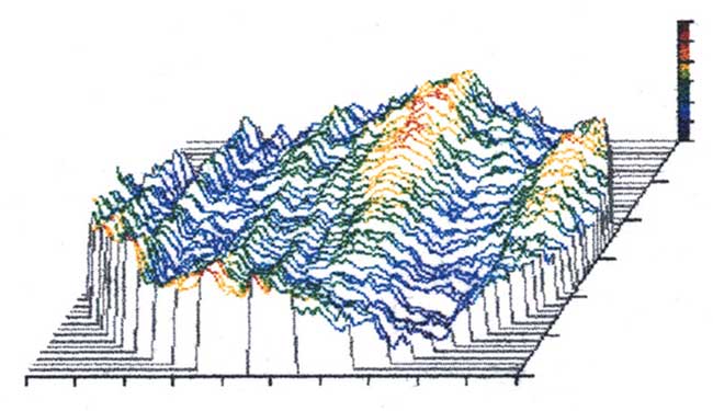 Figure 7. Typical surface roughness on germanium.
To further enhance the capabilities of the diamond turning machine, it should be fitted with a preloaded air-bearing spindle with a symmetrical thrust-bearing design and active thermal cooling. Because air-bearing spindles have no metal-to-metal sliding or rolling contact, they have low vibration. They also offer extremely low and repeatable friction. This means that thermal growth is minimal and there is virtually no wear during spindle operation. Also, like hydrostatic oil-bearing slides, air-bearing spindles have a tremendous bearing-averaging effect. This means that spindle rotation, in addition to being virtually friction free, is extremely smooth. This smoothness, combined with a radial and axial runout of 50 nm or less, significantly contributes to producing the highest quality workpiece accuracies.
To achieve the required machining resolution for optical fabrication (8.6 nm or less) slide positioning and velocity control should be accomplished through the use of linear glass scales in conjunction with sophisticated servo control systems. Linear glass scales are not susceptible to changes in barometric pressure or relative humidity.
For machining complicated optical components, particularly aspherics, it is necessary to utilize a computerized numerical control system on the machine. The CNC system is easy to operate and user friendly. It is responsible for controlling a machine’s functions as well as executing all part programs.